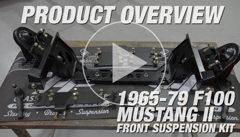
This is everything you need to know to install a CPP Deluxe Mini Sub-Frame Kit in a 1962 through 1967 Chevy II or Nova. If you’re more the video type, you can watch R&D Lead Jason Scudellari walk through the whole process. If you do better with written instructions and photos, we’ve also got you covered below.
Why Choose a Mini Sub-Frame Kit?
Still trying to decide what setup is best for your early Nova? That’s ok too. You can check out this video where we go over our ideal front suspension and steering upgrades for ’62-’67 Chevy II Novas.
Order Your Mini Sub-Frame Kit HERE
Instructions for Part Number 6267TCA-K
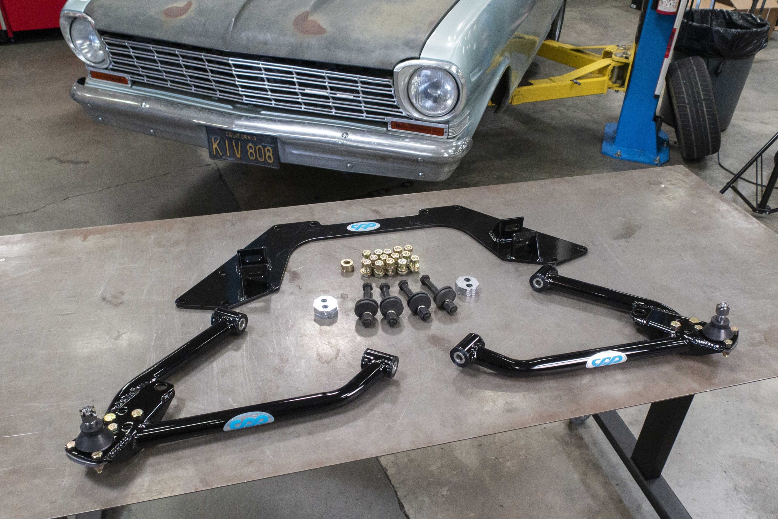
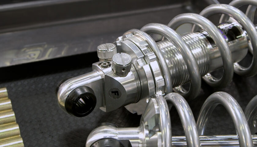
Options: CPP recommends using the coil over spring and shock kit part numbers 6267COK-SA single adjustable shock and 6267COK-DA double adjustable shock. CPP also recommends the tubular upper arm kit part number 6267TCA-UK.
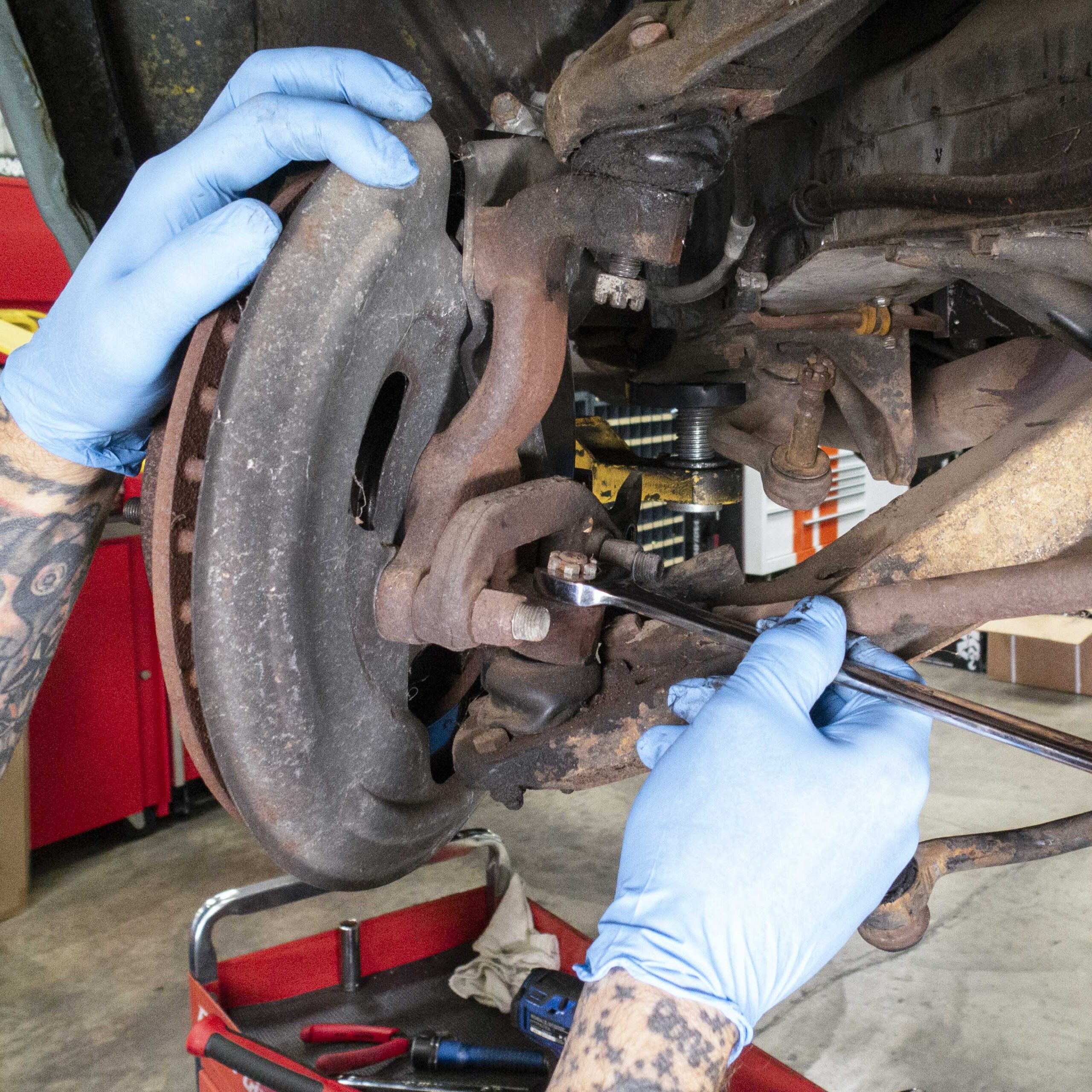
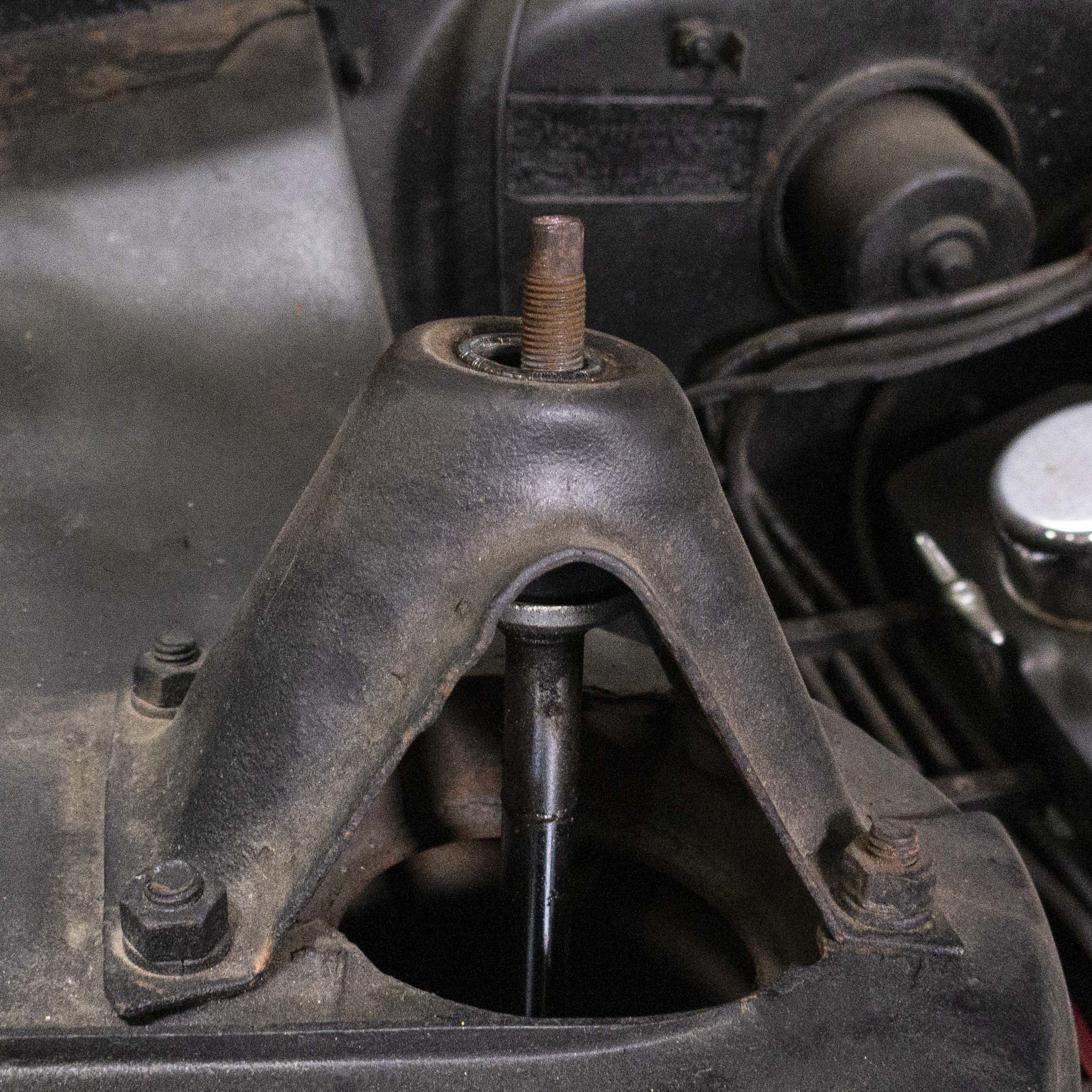
1. Begin by removing the ball joints from the spindle. Loosen the castle nut on the ball joint stud but leave it installed a few turns. A handful of whacks with a large hammer usually does the trick to break the ball joint stud loose from the spindle.
Installation Note: If you plan to also install CPP Tubular Upper Control Arms (#6267TCA-UK), now would be a good time to remove the brake caliper and tie rod end from the spindle as well.
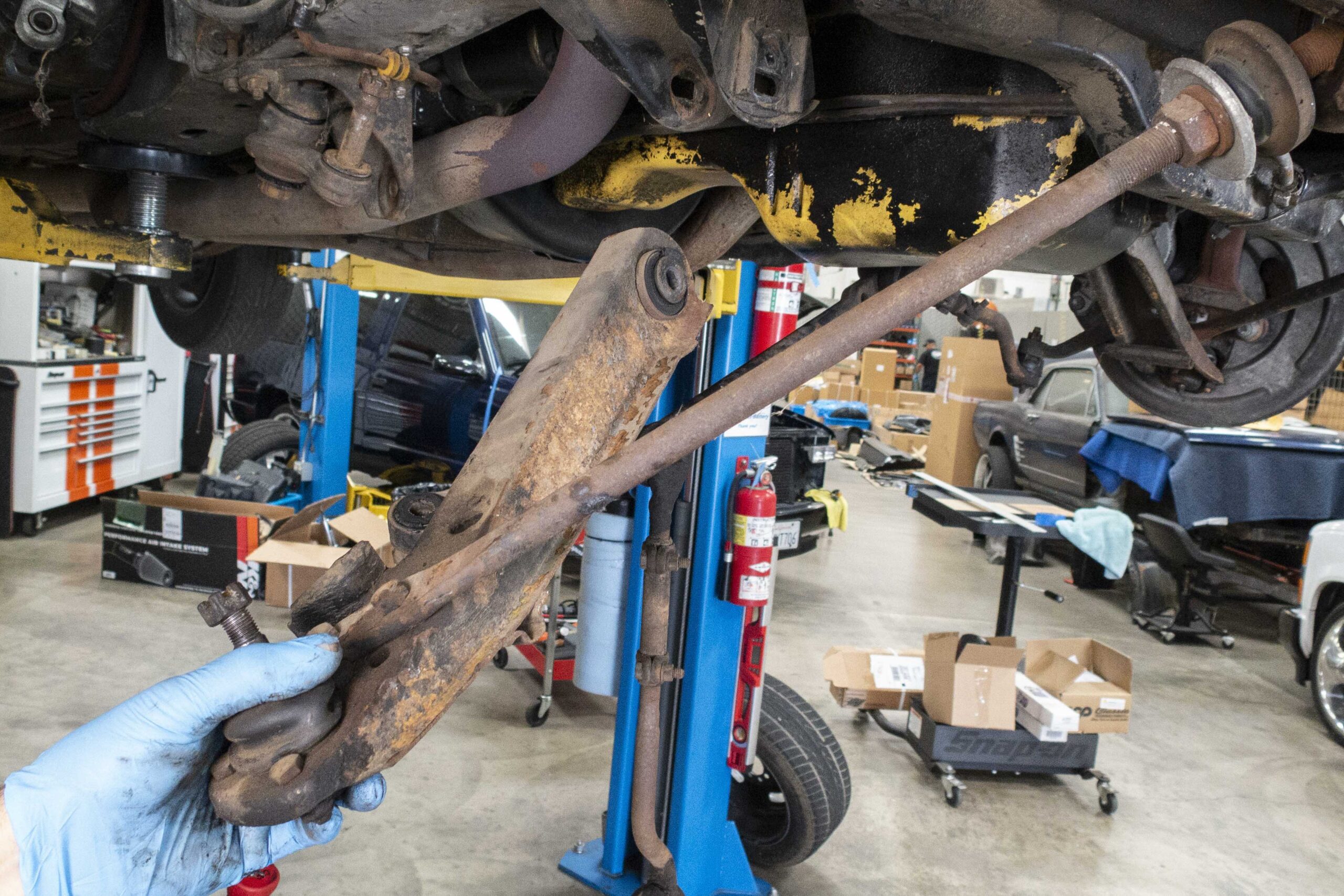
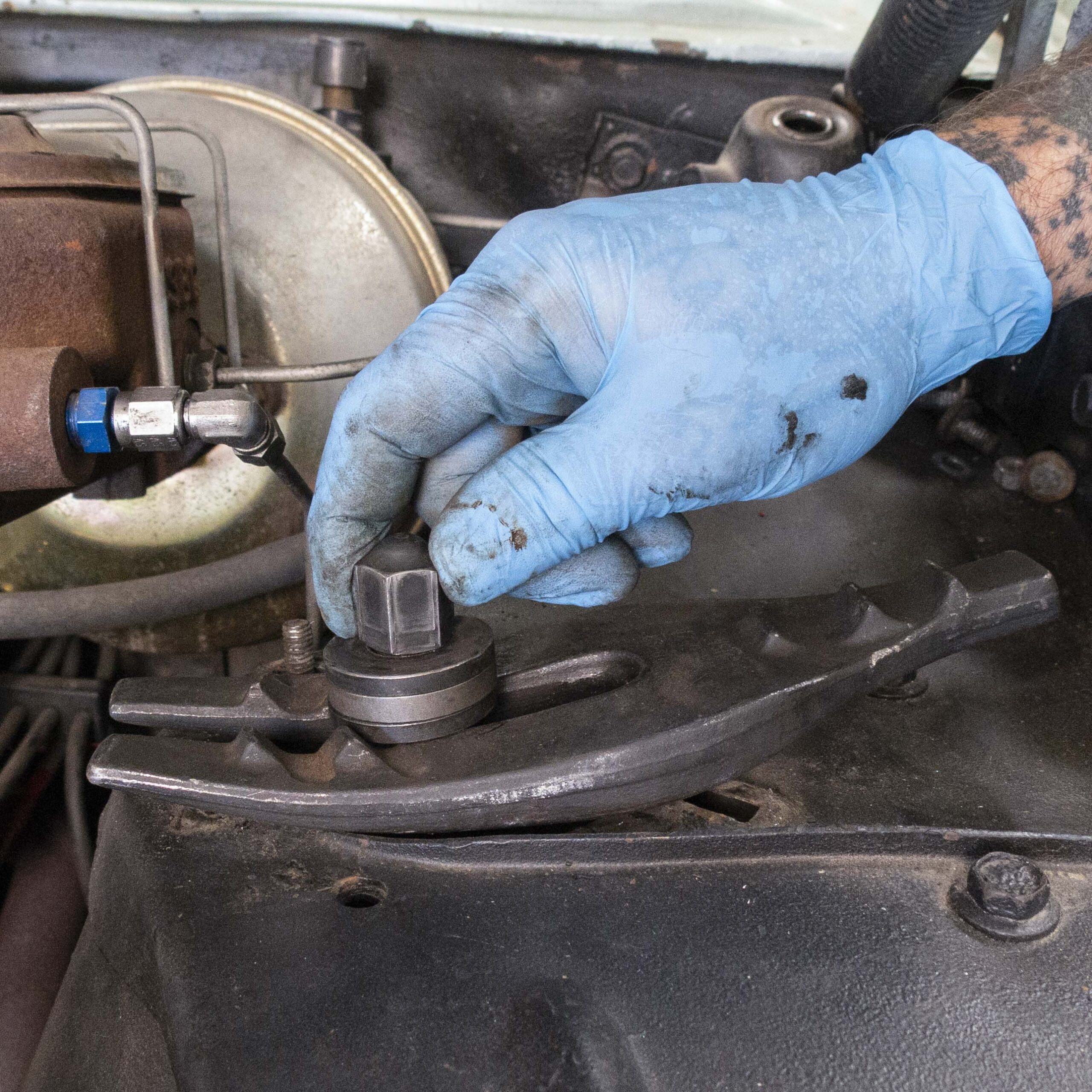
2. Then remove the front strut rod nut followed by the lower control arm bolt and remove the assembly as one piece.
3. Repeat steps 1 and 2 on the other side.
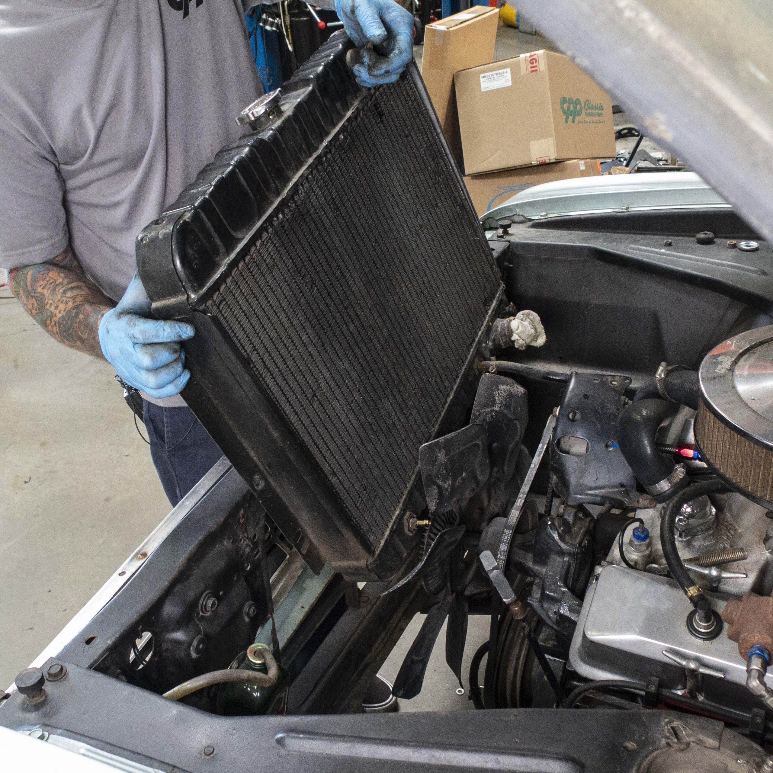
4. Next, drain the coolant from the radiator and remove it from the vehicle.
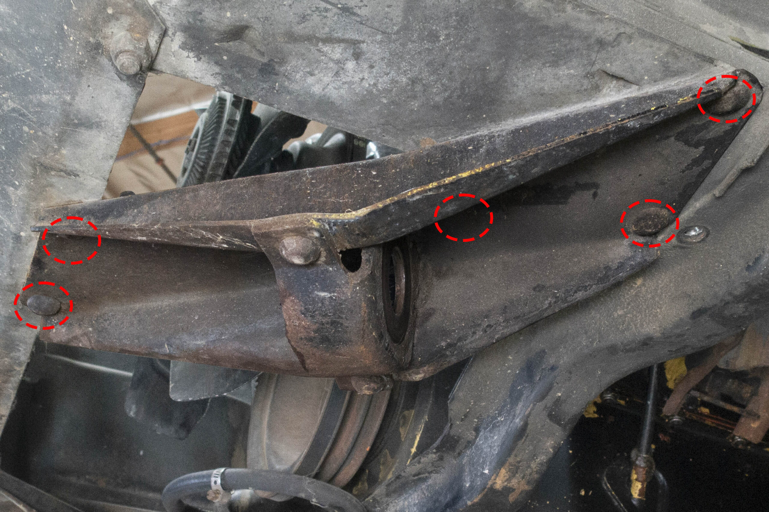
5. Prepare to remove the factory strut rod mounts on both sides. Each mount is held in place with five rivets.
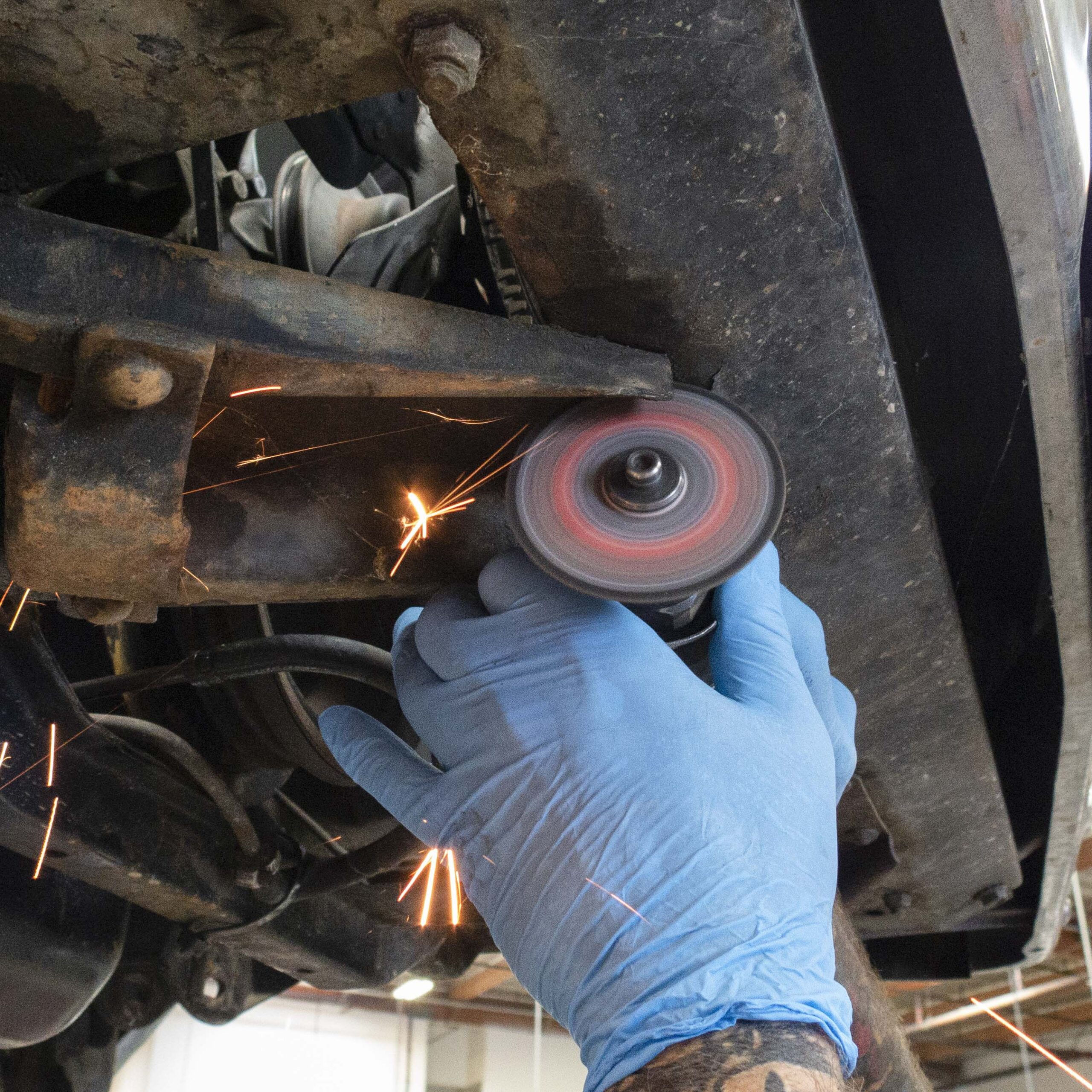
6. The most effective method we’ve found for removing old rivets is to cut them down the center with a cutoff wheel.
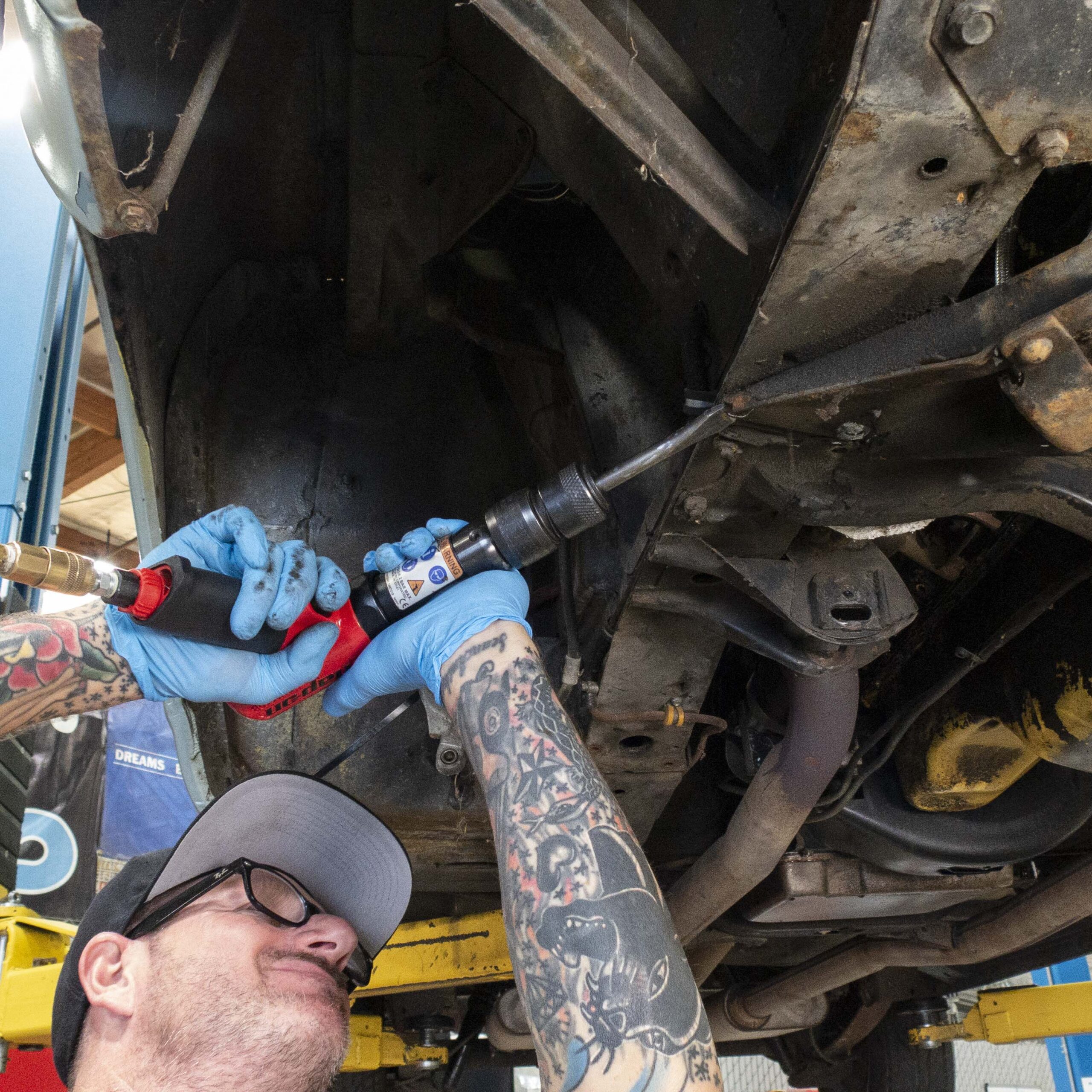
7. Then remove the rivet head with an air hammer and drill out the remains.
Note: Without access to an air hammer, the same can be accomplished using a hammer and chisel; although significantly more effort will be required.
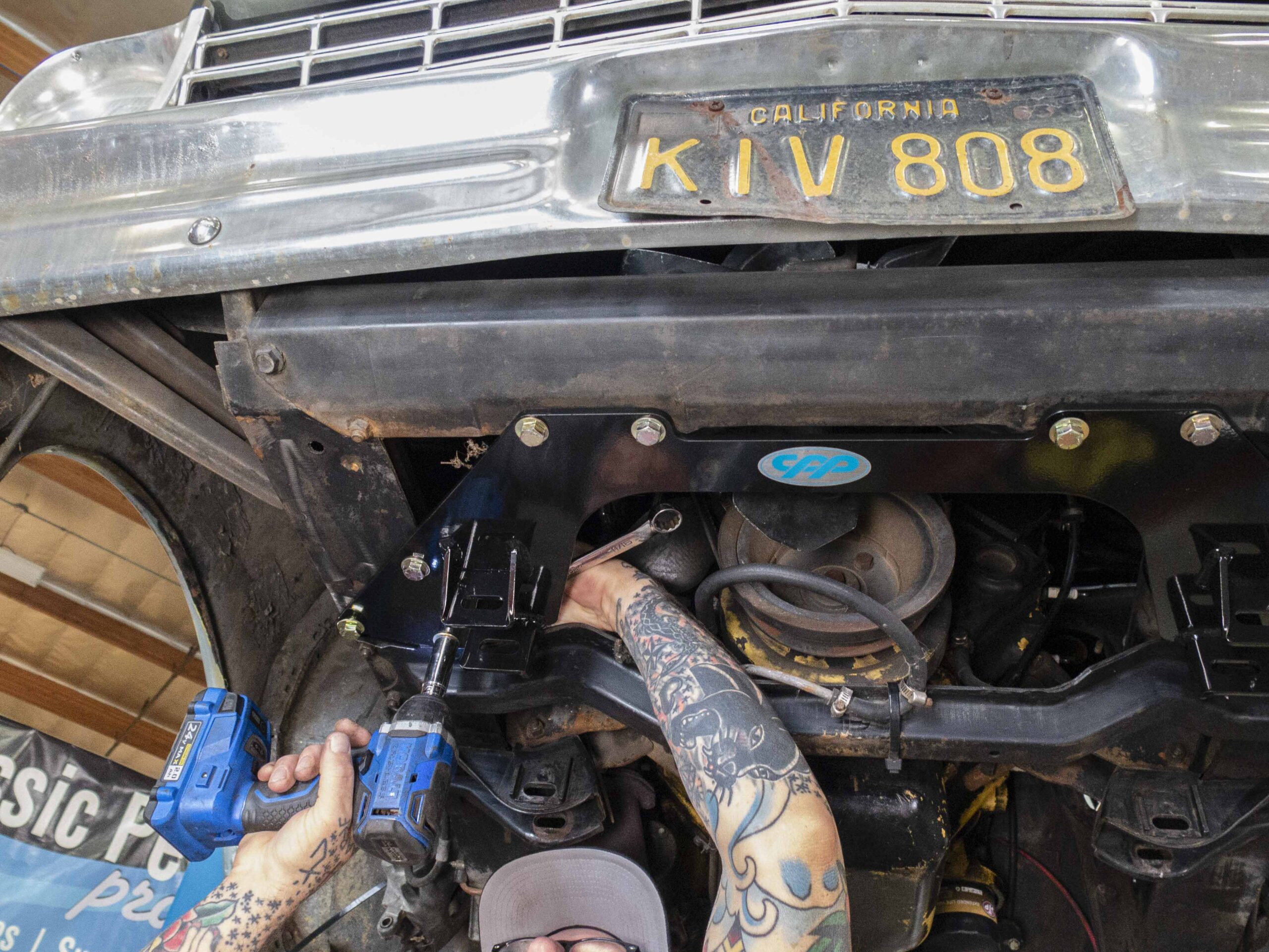
8. Install the Mini Sub-Frame plate using the supplied hardware in the 10 holes left from the rivets.
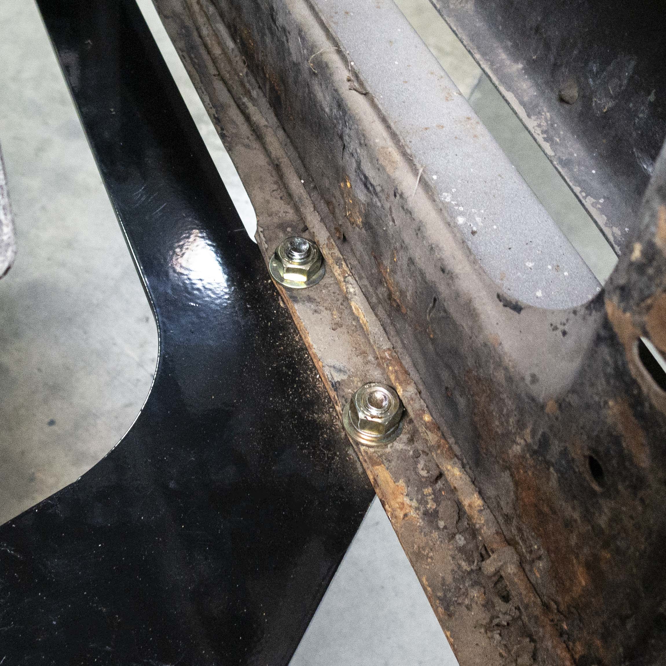
9. Test fit your radiator, checking for clearance against the front four bolts.
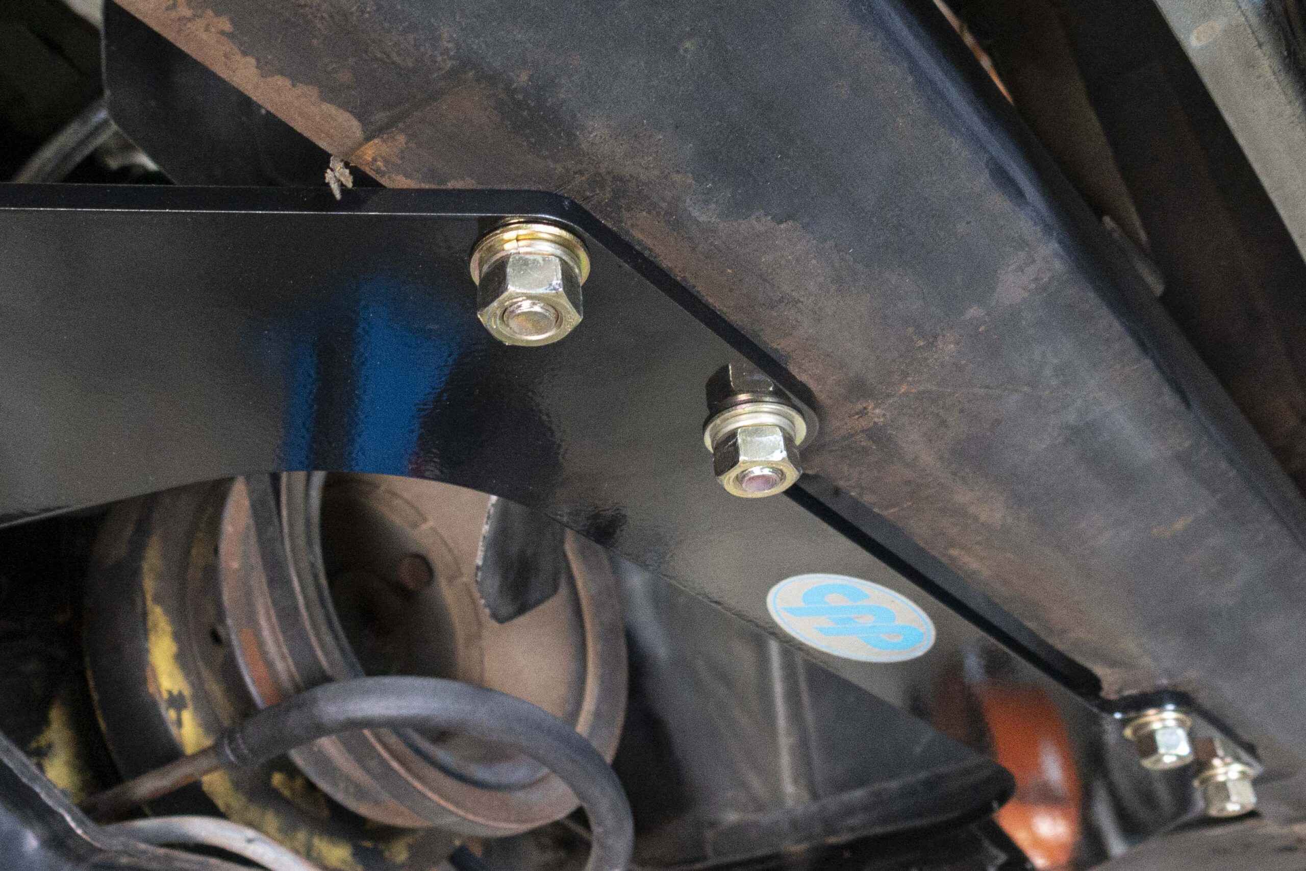
10. If more room is needed to keep the radiator from touching the Mini Sub-Frame hardware, simply remove the front four bolts and nuts then re-install with the nuts on the bottom side of the crossmember as shown.
11. Torque all crossmember hardware to spec.
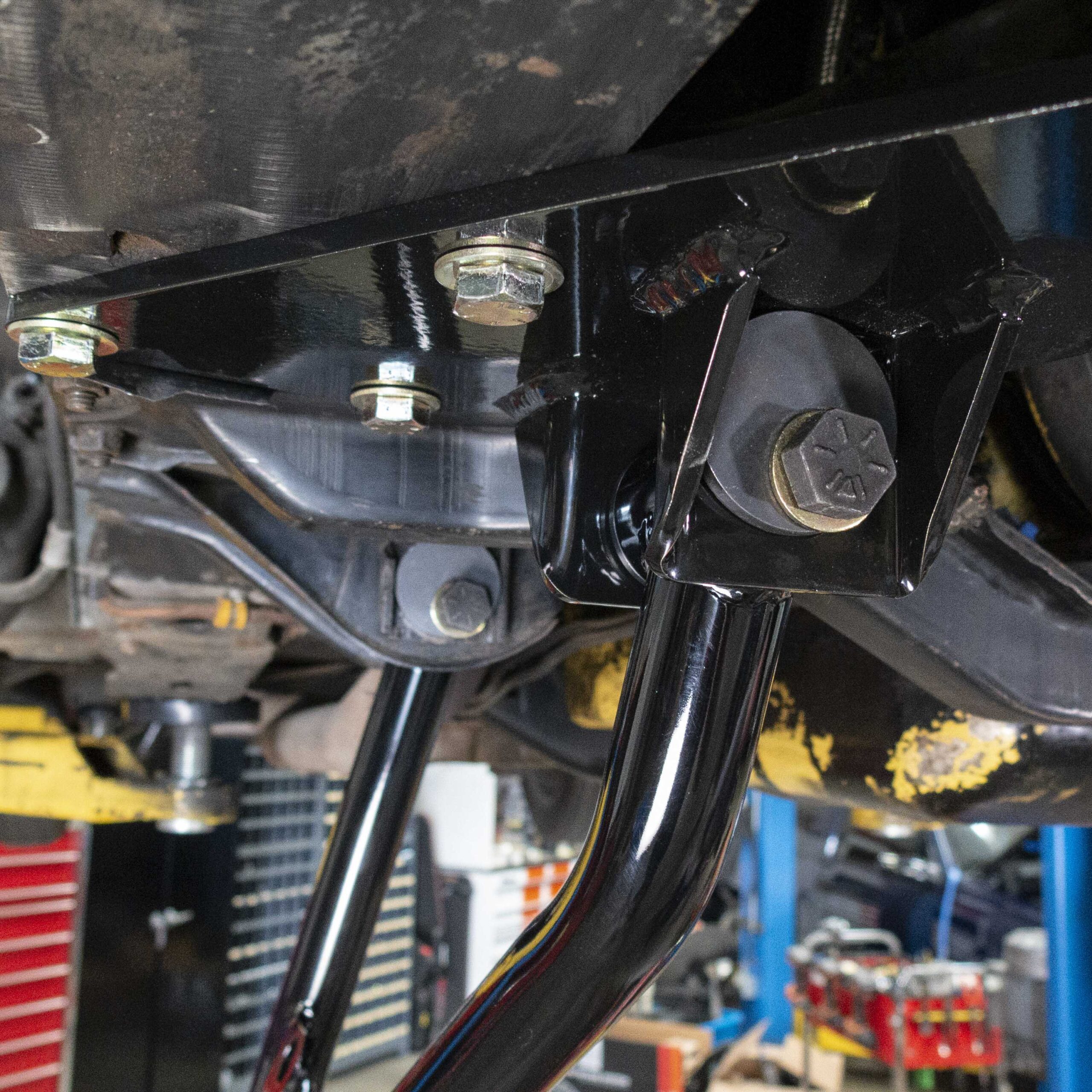
12. Next, use the supplied bolts, washers and cam washers to install the tubular lower control arms. The front of the arm goes in the new crossmember and the rear of the arm goes into the factory lower control arm mount.
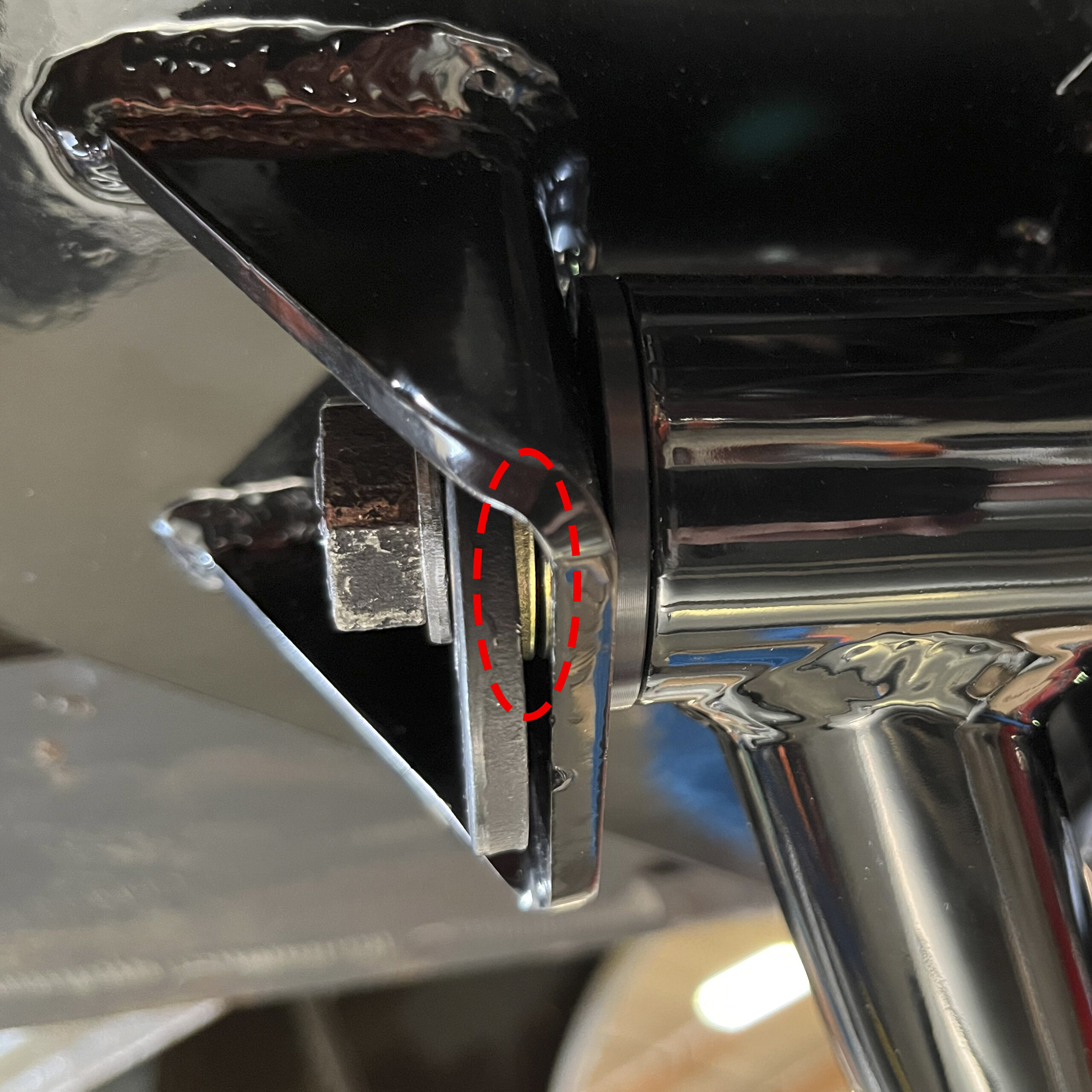
13. Make sure to use a washer between the cam washer and the mounting surface on each of the four sides. Failing to do so may result in the bolts slipping and going out of alignment.
14. Repeat steps 10 through 13 on the other side.
Optional Installation Tip: Provided with every Mini Sub-Frame Kit are a set of lockout plates (#CP10134). These may be installed after the vehicle has been professionally aligned to ensure the alignment cannot go out of spec during hard driving.
Instructions for Part Number 6267TCA-UK
Options: CPP recommends using the coilover spring and shock kit; part numbers 6267COK-SA for single adjustable shock and 6267COK-DA for double adjustable shock. CPP also recommends the tubular lower arm conversion kit part number 6267TCA-K
Installation Notes:
- These control arms are 3/16” shorter than stock in order to provide a larger range of adjustment. It may be necessary to shim the cross shafts.
- When using drop spindles, the brake calipers can come in contact with the upper control arms during steering. To remedy this problem, we suggest using part numbers 31948 and 31947 which will rotate the brake calipers out of the way.
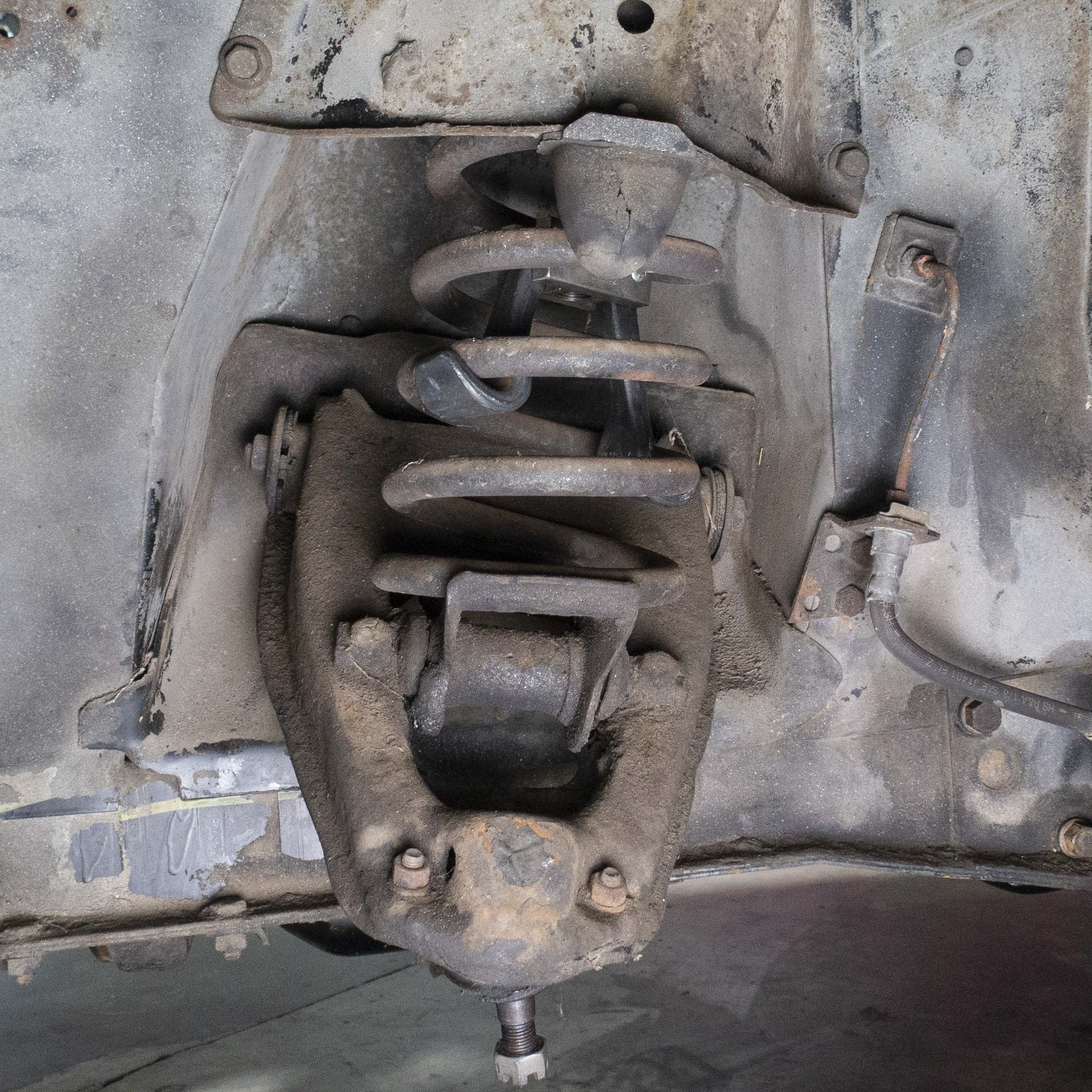
15. Remove the shocks from the vehicle by removing the upper and lower shock mounts and the shock tower brackets.
16. Use a spring compressor to compress the spring, relieving pressure on the upper control arm.
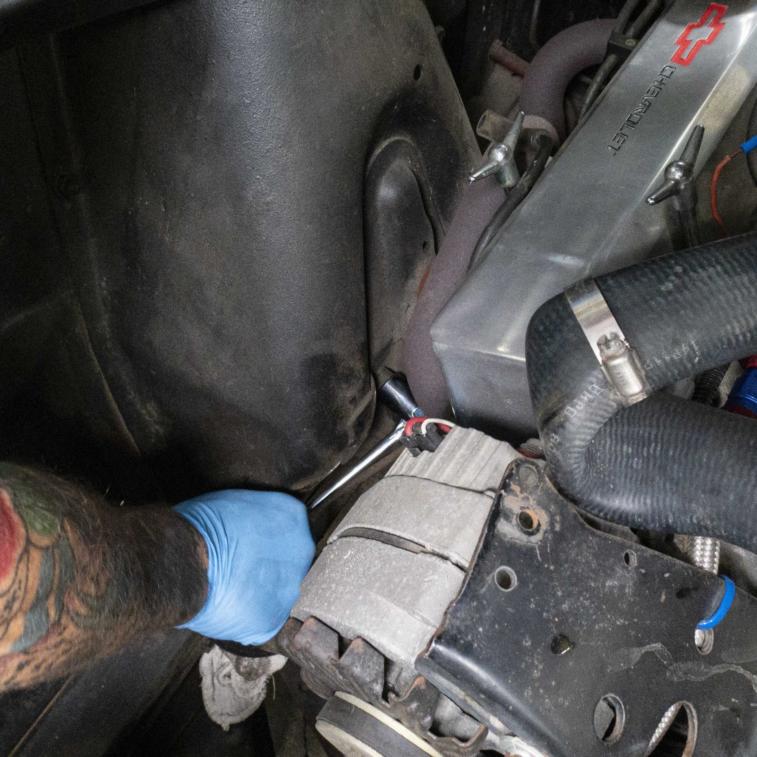
17. To remove the upper control arm, undo both bolts on the engine bay side of the shock tower.
18. Once the control arm has been removed, proceed to release tension on the spring and remove from the vehicle.
19. Repeat steps 16 through 19 on the other side.
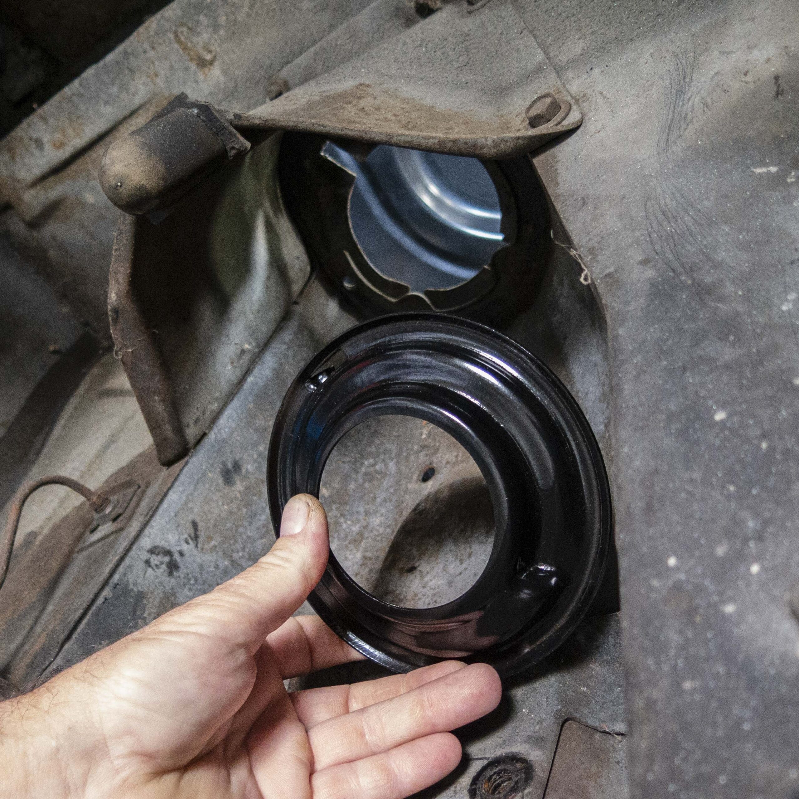
20. We suggest replacing the spring retainer plates (part number 6267CRP). Simply lift the plate into place and then a small turn will lock it in.
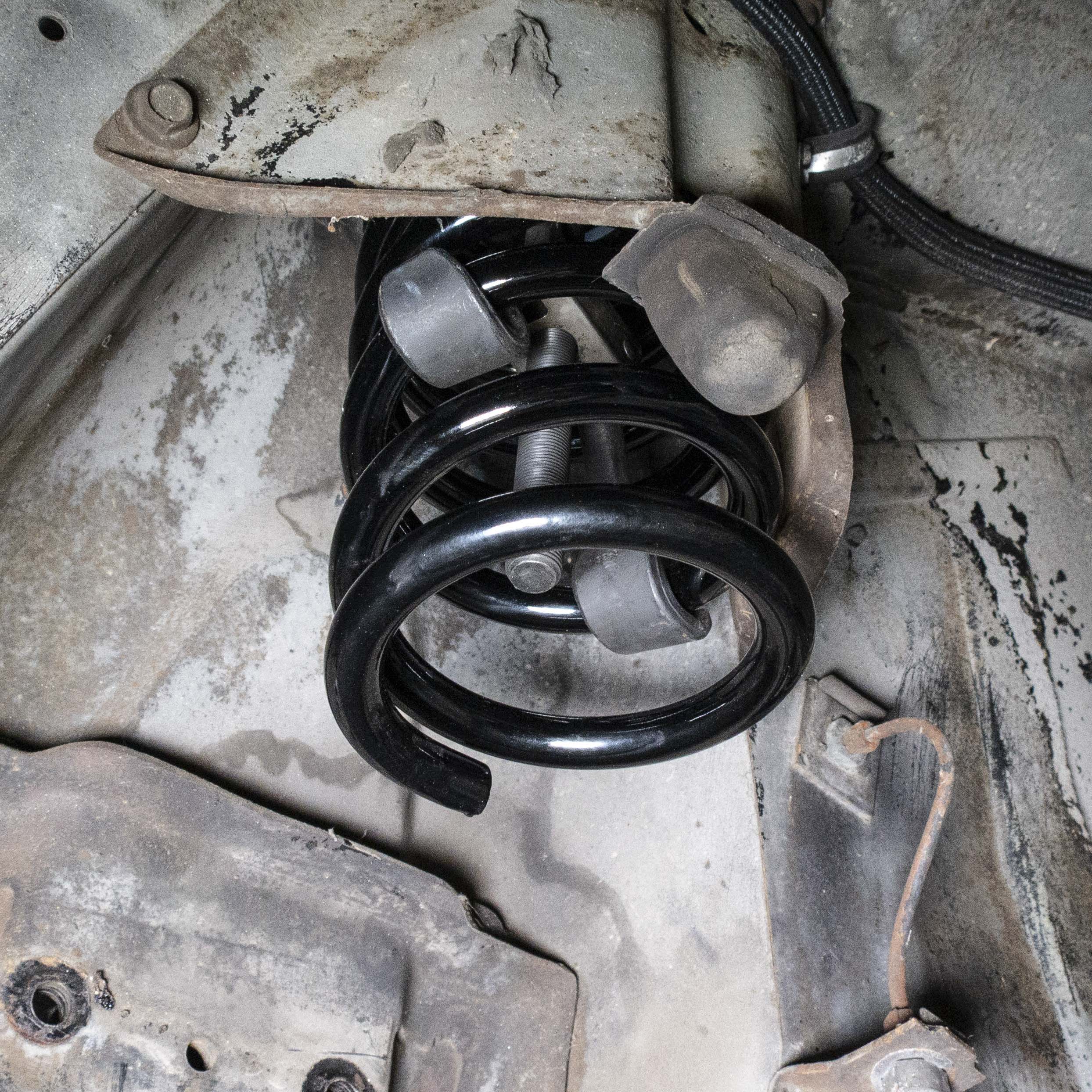
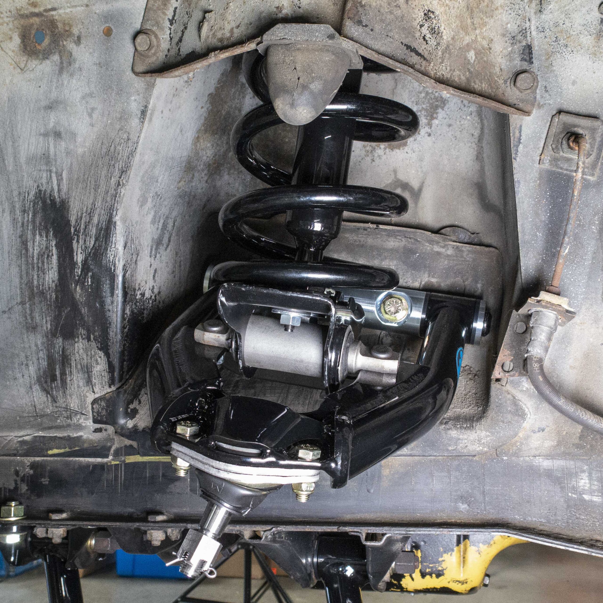
21. Whether installing a stock or dropped spring, use the spring compressor to hold the new spring up out of the way while installing the new control arms.
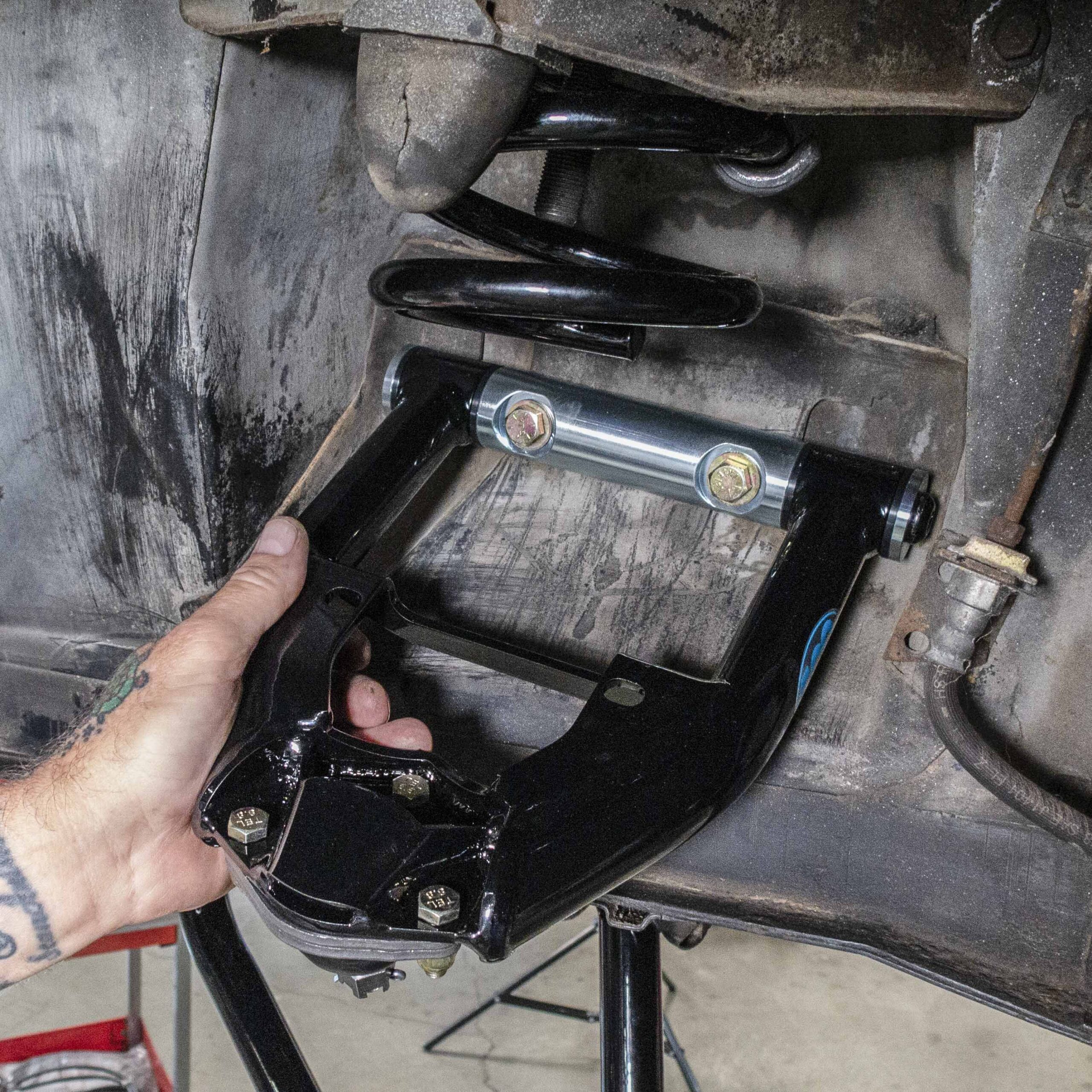
22. Install the new control arm using the supplied hardware.
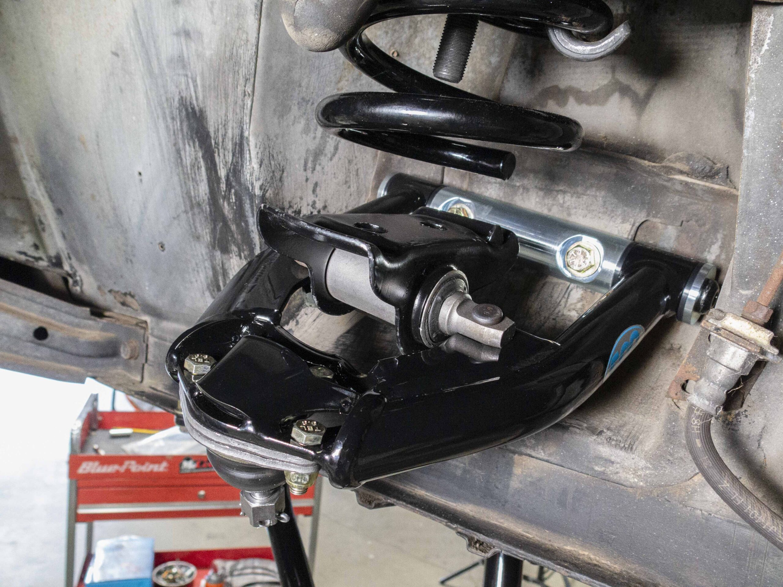
23. Next, install the coil perches. CPP recommends using new coil perches; part number 6267PCH-R for rubber or 6267PCH-P for PolyPlus.
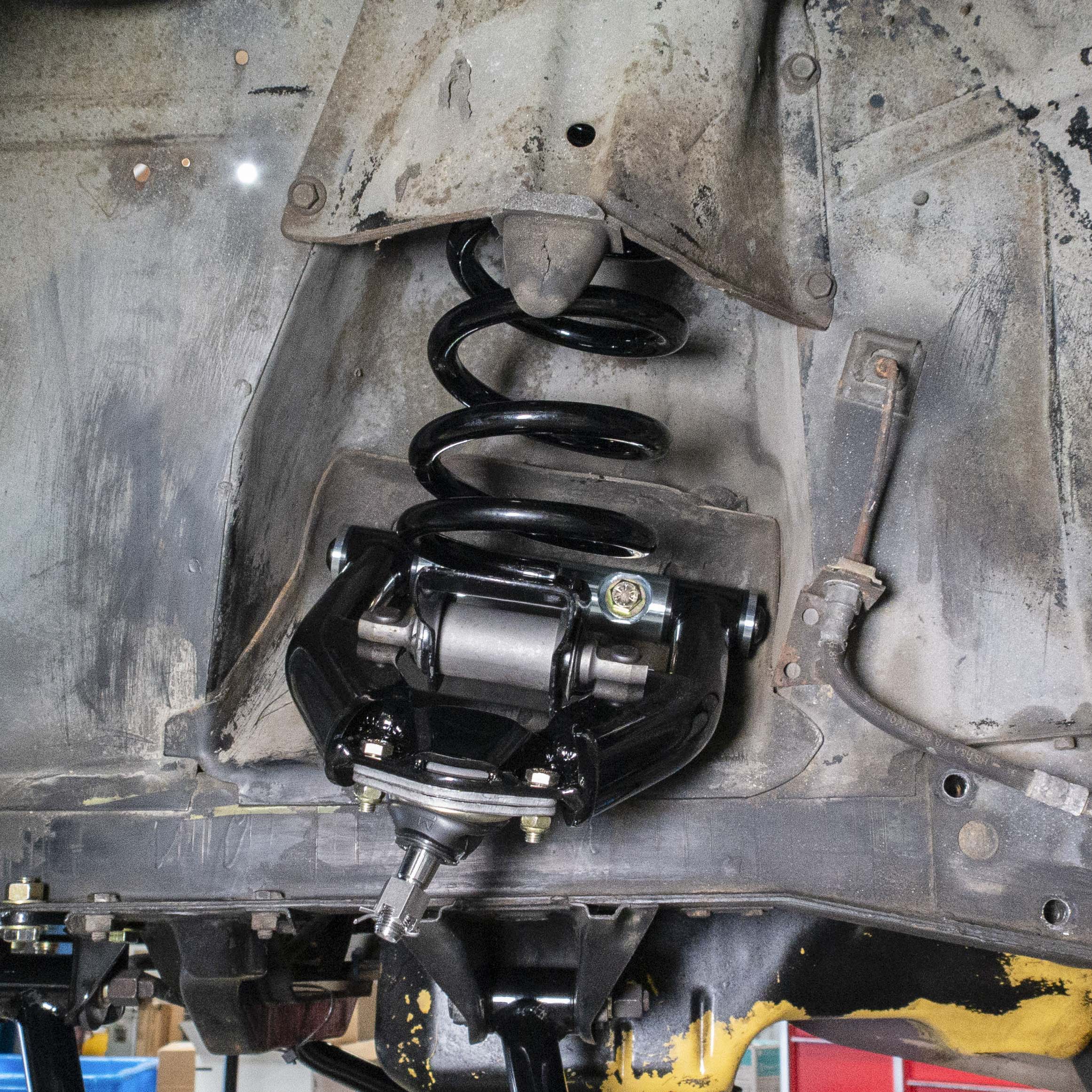
24. Ensure the spring is properly oriented in reference to the locating tab on the spring perch, then slowly release the tension on the spring.
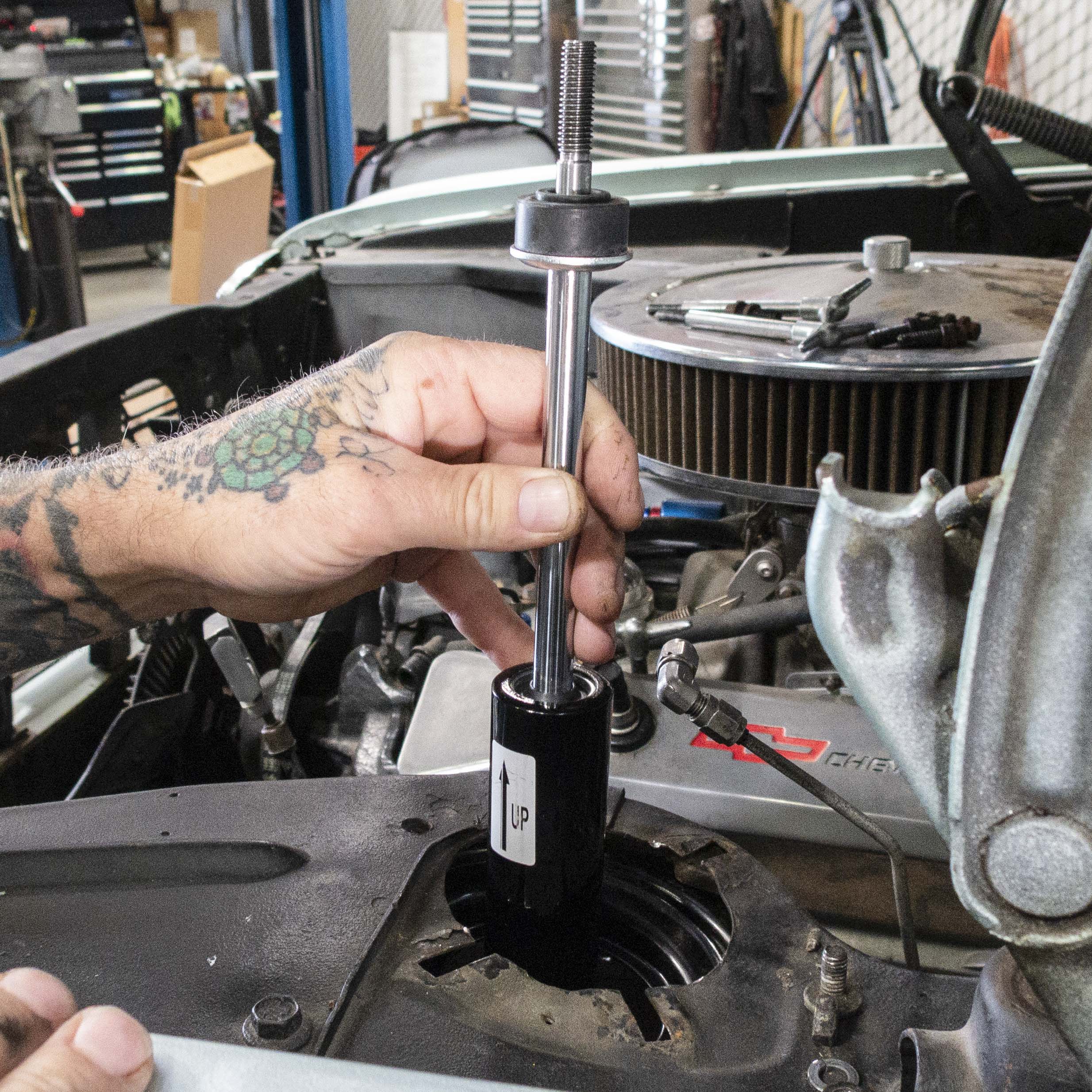
25. Install the new shock into the shock tower.
26. Fasten the shock to the spring perch using the supplied hardware.
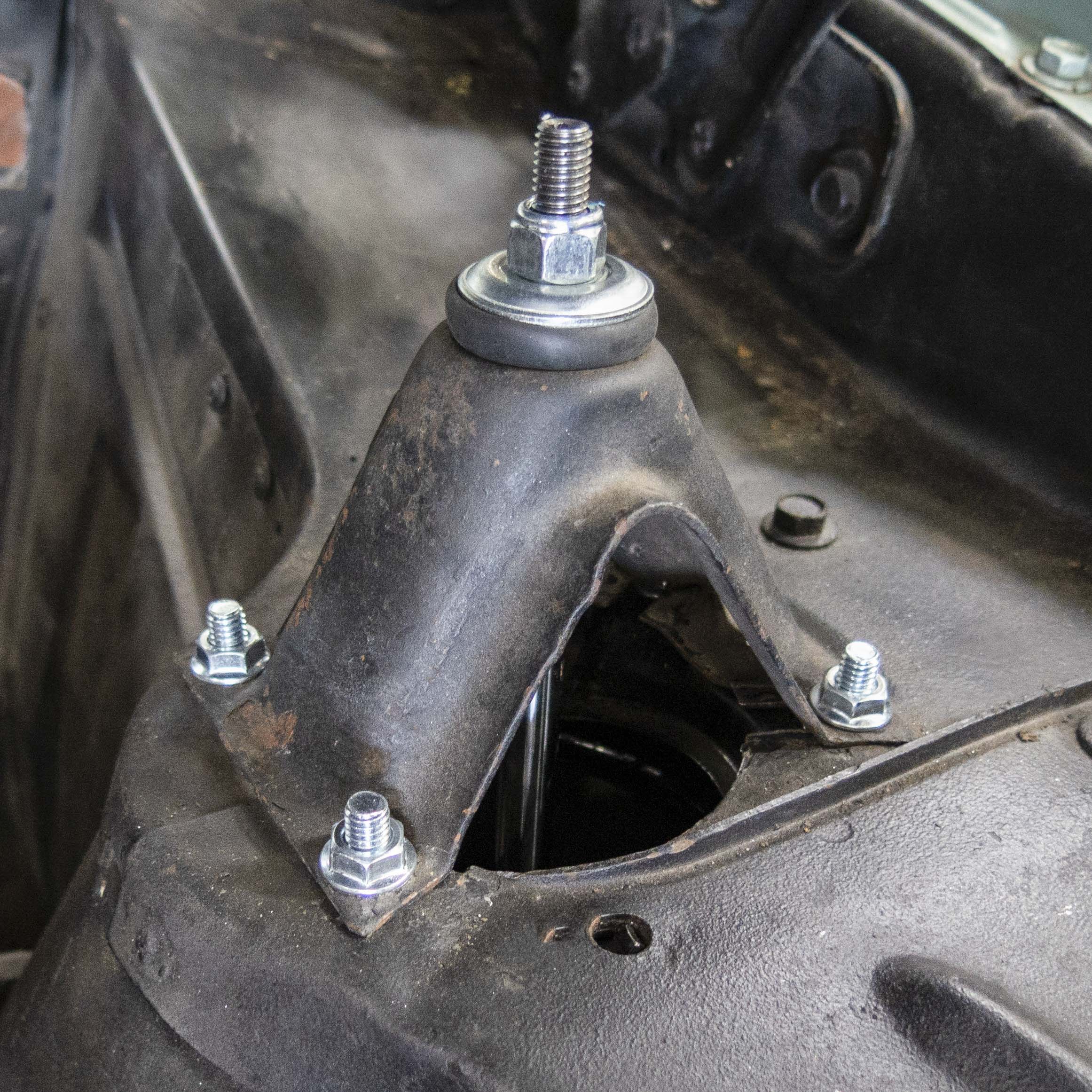
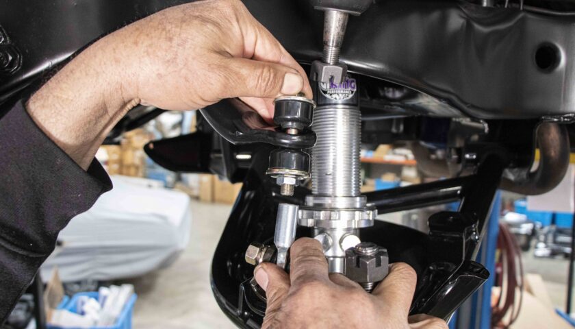
27. Put one of the supplied washers on the top of the shock followed by a bushing. Then re-install the shock tower, add another bushing and washer to the top of the shock, and finally secure with a nut.
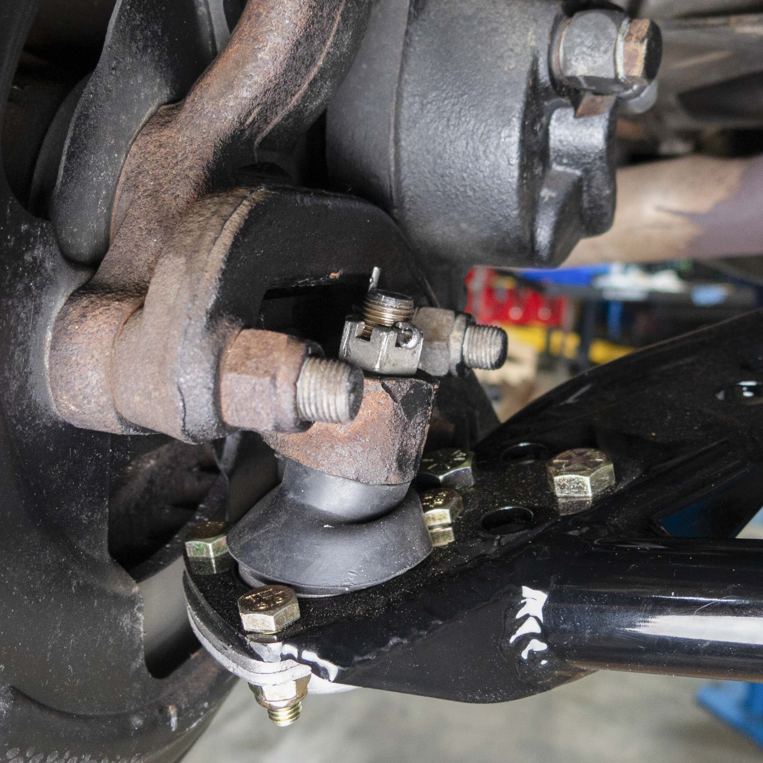
28. Reinstall the upper and lower ball joint stud into the spindle followed by the tie rod end. After fully tightening the castle nuts, make sure to install a new cotter pins.
29. Repeat steps 21 through 29 on the other side, then have the vehicle professionally aligned.

[…] Related Story: How to Install CPP Mini Sub-Frame Kit: 1962-67 Nova […]
[…] Related Story: How to Install CPP Mini Sub-Frame Kit: 1962-67 Nova […]