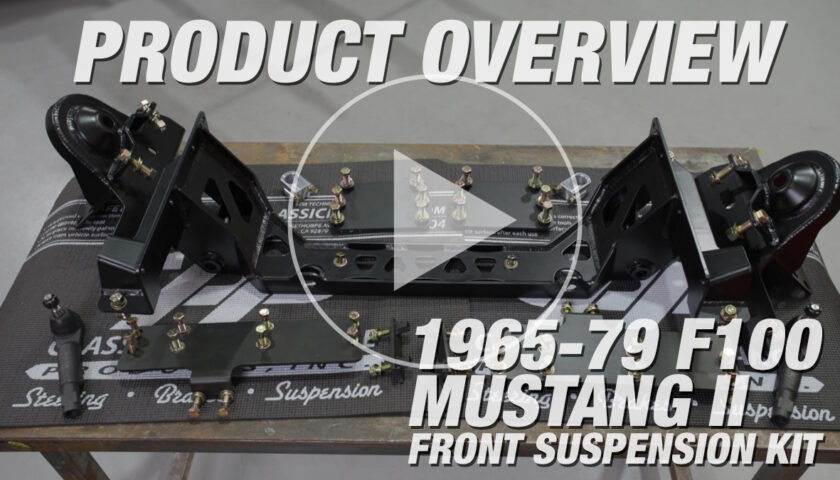
If you’re in the market for a front sway bar, there are a few options out there but none that tick all the same boxes as the CPP High Clearance Adjustable Front Sway Bar. In the above video, Jason Scudellari will walk you through some of the benefits and show you step-by-step how to install one of these sway bars.
If you prefer detailed instructions with photos, you can find those below.
See more of our 1963 Nova project here
Features and Benefits of the High Clearance Adjustable Front Sway Bar
- Laser cut arms provide maximum wheel and tire clearance
- Two rod end mounting locations for adjustable stiffness
- 1.25” hollow bar is stiffer and lighter than a traditional sway bar
- Grease pockets in the D-Spec bushings for extended service life
- Billet mounts available
- Great value at a low price point
Related Story: How to Install CPP Mini Sub-Frame Kit: 1962-67 Nova
Installation instructions for CPP High Clearance Front Sway Bar 6267HCSBK-125
Preparing the Sway Bar for Installation
1. Before beginning the install, note the inside of the supplied sway bar mount bushings. The pockets in the bushings are designed to retain grease for extended service life.
2. Begin by installing one bushing near the end of the sway bar tube in preparation for mounting the bar to the chassis.
3. Slide the billet mount over the bushing, then the two bolts, then the mounting plate, then the two bolt spacers.
Mounting the Sway Bar to the Chassis
4. Hold the bar up into place against the chassis crossmember and mount the bar utilizing the existing holes. Use the supplied Nylock nuts to secure the sway bar mount.
5. Use a wrench to hold the Nylock nuts while tightening the bolts from the bottom.
Attaching the End Links on the CPP High Clearance Adjustable Front Sway Bar
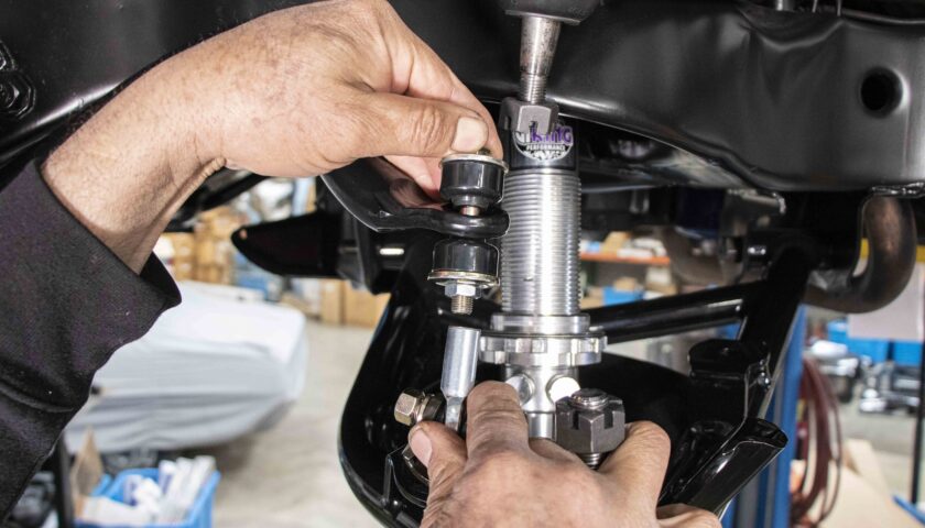
6. Once both sides of the sway bar have been mounted to the chassis, the next step is installing the end links. With a rod end on top and bushings on the bottom, the sway bar works with the factory lower control arm or CPP Tubular Control Arms.
7. Begin assembling the end links with a bolt, washer, and bushing on the bottom of the control arm; then a bushing, washer and jam nut on top.
8. Next, install the rod end but leave it loose until both end links have been installed.
Installation Note: The stiffness of the sway bar can be adjusted by switching the installed location of the end link on the laser-cut arms. Installing the end link using the hole closest to the sway bar tube will result in a slightly stiffer ride while the hole further from the tube will yield a softer ride.
9. Using the supplied hardware, attach the rod end to the laser-cut sway bar arm in one of the two holes.
10. Once both end links have been installed, proceed to tighten the jam nuts; then tighten the rod ends.
11. Complete the installation by greasing the two sway bar mount bushings.
Want video instructions for this sway bar? Check out our YouTube video here!
[…] How to Install CPP High Clearance Adjustable Front Sway Bar for 1962-67 Nova […]