This tech story is brought to you by our friends over at All Chevy Performance Magazine. Check out a preview of the September issue of the magazine here and then go support them by signing up for a digital and/or print subscription here!
Text and Photos by Jeff Smith
Intro to Proper Driveline Alignment
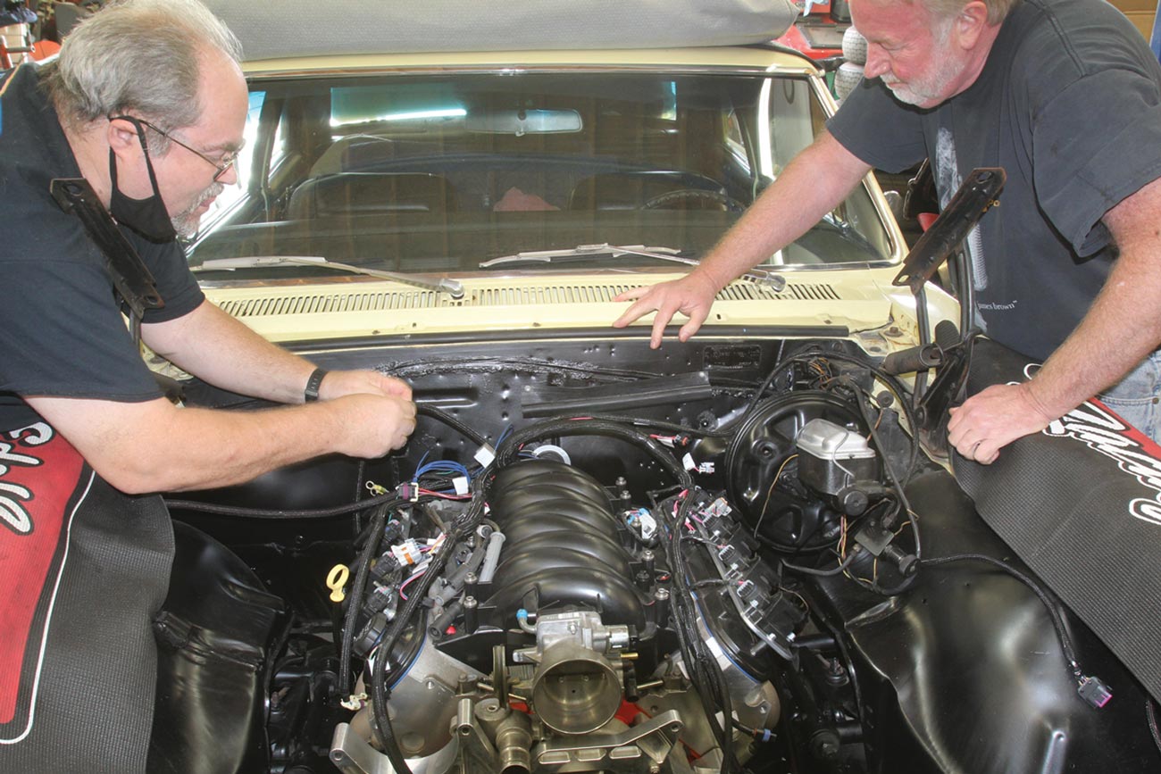
Engine and driveline swapping has long been a staple of building performance cars since the first rodders began swapping parts in the back of a blacksmith’s shop. Today’s market is full of LS swap parts, upgraded transmissions, and a myriad of rear axle opportunities. But along with all this parts customizing is the reality of ensuring all these parts work together, so your upscale machine sings along nicely on the highway. This is where proper driveline angle comes in.
Related Story: Best Bang-For-Your-Buck Nova Rear Suspension Setup
One area that is universally overlooked is the link between the transmission and the rear axle. Sure, you spec’d the length of that custom driveshaft right down to 1/8 inch and it now fits snugly in between the engine and rear axle. But is the angle correct? Just because the driveshaft doesn’t vibrate or rattle the inside rearview mirror off its mount on deceleration doesn’t mean the driveline angle is correct. It’s really something that should be verified.
To minimize the confusion around measuring the driveline operating angle, TREMEC has come up with a slick smartphone application to measure and compute the operating angles for you. It turns out that a proper operating angle has a very specialized set of requirements.
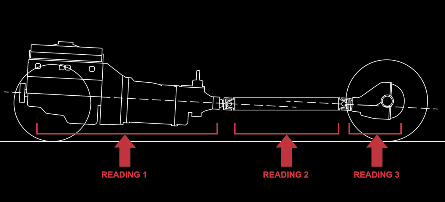
Imagine we are looking at the driveshaft from the driver side of the car with Superman X-ray vision looking at three separate operating components. The first is the engine and transmission angle that we will combine into the first module. The second is the driveshaft itself and the third is the pinion angle of the rear axle. Generally, the engine/transmission module will be positioned with the output shaft of the transmission lower than the front of the engine by anywhere from 2 to 4 degrees.
If we jump to the rear axle, we will focus on the pinion angle that we will express as having either a nose-up or nose-down angle. In order for the driveshaft U-joints to perform their job properly, they must operate within a narrow set of angles. The key to all of this is to orient the entire driveline with the engine/transmission and rear axle pinion angles roughly parallel to each other.
The TREMEC illustration in their app reveals this relationship, which should help you visualize what needs to happen. What we want to avoid is the engine/transmission and rear axle operating at large intersecting angles. However, this may not always be possible. If the angles intersect, as between the driveshaft and the pinion angle, it’s important that the total operating angle not exceed 3 degrees. If the angle exceeds 3 degrees this will cause a vibration. With all this as our goal, let’s look at how to measure and calculate the operating angles.
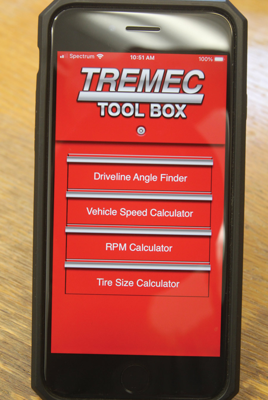
TREMEC Toolbox App: Driveline Angle Finder
Most gearheads know about the TREMEC transmissions company. They manufacture several lines of high-performance five-, six-, and now seven-speed manual transmissions that are found both in OE and aftermarket vehicles. A number of years ago they began dealing with complaints about driveline vibrations that occurred after a new transmission was installed. The installers assumed there was an issue with the transmission when the problem was more often traced to poor driveline operating angles.
To remedy this situation, TREMEC developed a free driveline operating angle checking application for both Android and iPhones that runs through a simple set of angle measurements and then calculates the entire operating angle in a report. You can find this app by visiting tremec.com, click on Aftermarket, and then click on TREMEC Toolbox App.
Driveshaft Basic Rules
| 1. The minimum operating angle of each individual U-joint should not be less than 0.5 degree. |
| 2. The operating angles on each end of the driveshaft should be within 1 degree of each other. |
| 3. The total operating angle from the engine to the rear axle should not exceed 3 degrees. |
Driveline Angle: Deep Dive
Before we get into the TREMEC app, it’s important to emphasize the ultimate goal for measuring these angles. Driveline engineers long ago determined that an operating angle at either U-joint of more than 3 degrees is excessive and will cause a vibration. We found this information on spicerparts.com. If the angles are roughly parallel, the rule is to subtract the smaller angle from the larger one.
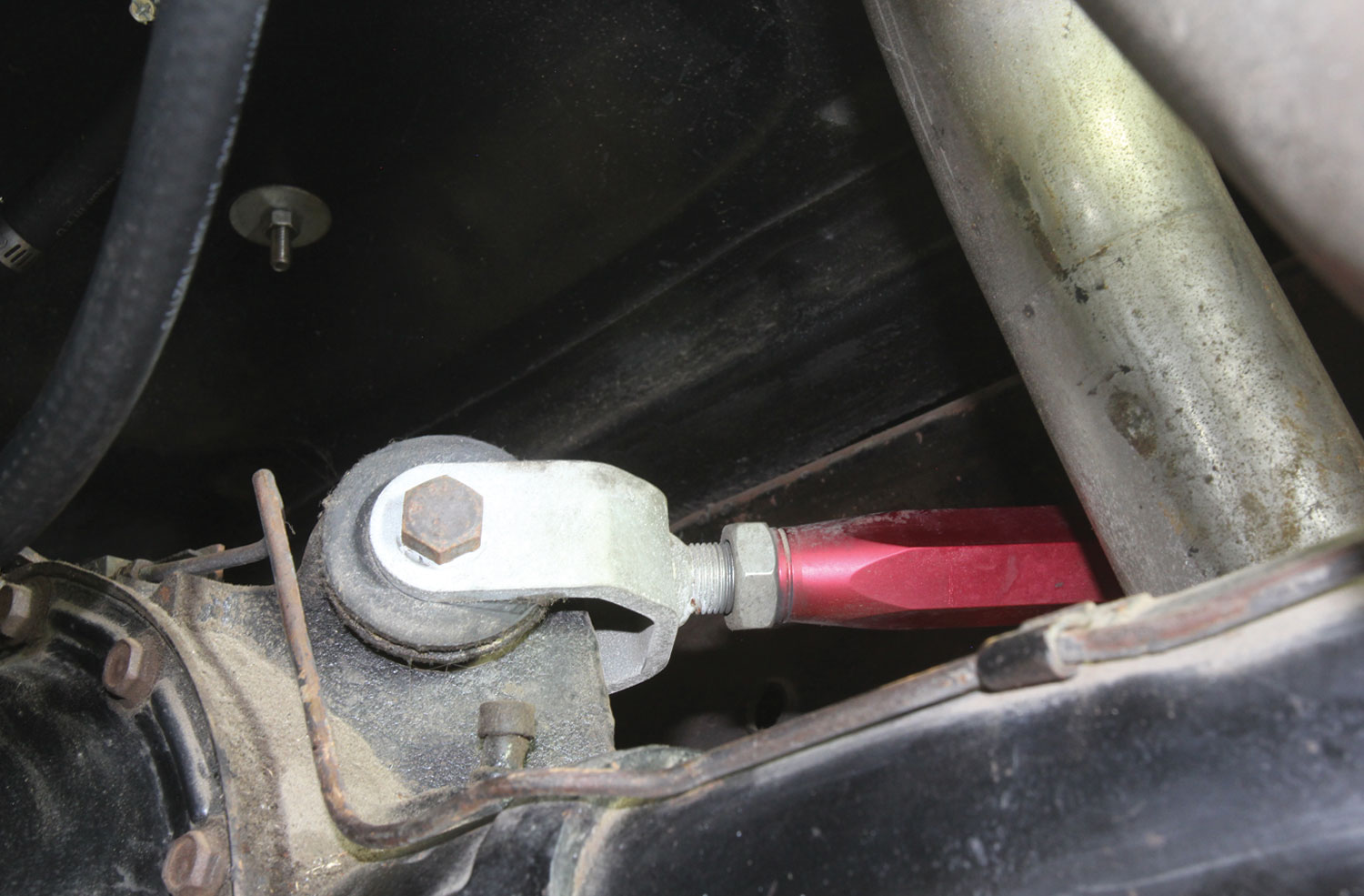
Let’s say that we then measure the pinion angle of the rearend and discover it is nose down by 1 degree. Keep in mind that the pinion is facing the opposite direction so a pinion down angle will intersect with a driveshaft down angle. Looking at these angles from the driver side of the car, the engine/transmission angle is sloping downward toward the rear. The imaginary line formed by the pinion is also sloping downward, creating intersecting angles. According to Spicer, this intersecting angle is not necessarily bad as long as it does not exceed 3 degrees. However, this intersecting angle is very sensitive to rpm, with the higher the rpm, the greater the potential for vibration.
In the case of intersecting angles, the rule is to add the two angles. With the above driveshaft angle of 1.0 degree and the pinion-down angle of 1.0 degree, this equal 2.0 degrees, which is within the acceptable range. However, if we spin this combination at a high rpm, it may in fact vibrate. This is one reason (there are others) why TREMEC has chosen this app to push for parallel angles.
TREMEC maintains an ideal driveline angle arrangement to create parallel lines within a total of no more than 2 degrees of operation between the engine/transmission and the pinion. This is most easily accomplished by replicating the tail-down angle of the engine/transmission with a parallel line created by an upward-facing pinion angle. These two angles need to be parallel within 2 degrees. So if the engine/trans is 2.5 degrees tail-down, then the pinion angle at ride height can be anywhere from 0.5 to 3 degrees nose up, which will create a total operating angle of parallel lines within 2 degrees.
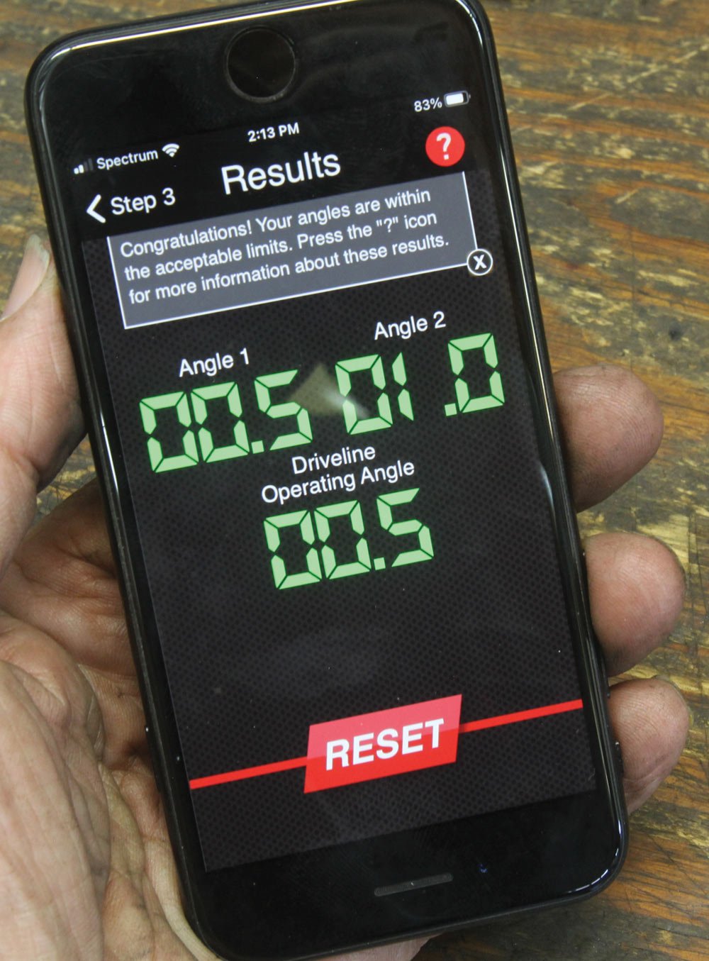
This has become a somewhat lengthy explanation but you should be able to see how the total operating driveline angle concept works. A few simple measurements will quickly give you an idea of your car’s operating driveline. You may discover, as we did, that while our car had not previously exhibited driveline vibration, it did measure out of spec. With some minor adjustments, we were able to bring the system into line. Think of this as blueprinting your driveline. It’s not overly complicated and the extra effort will make your driveline happy and will certainly contribute to a longer life on the road.
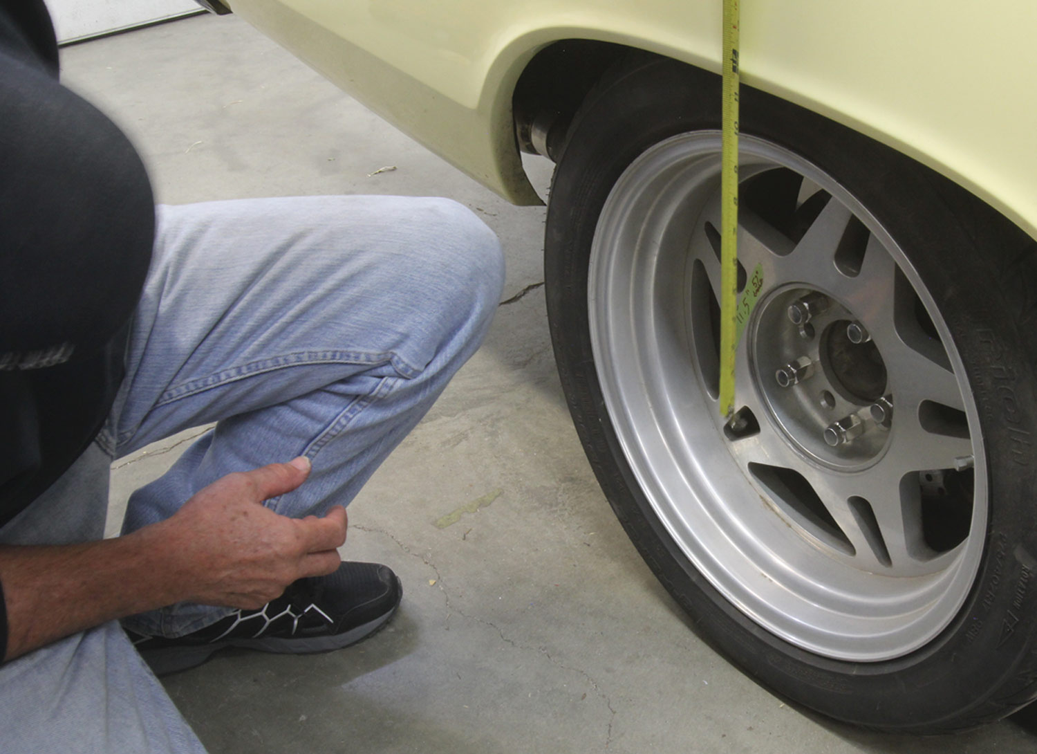
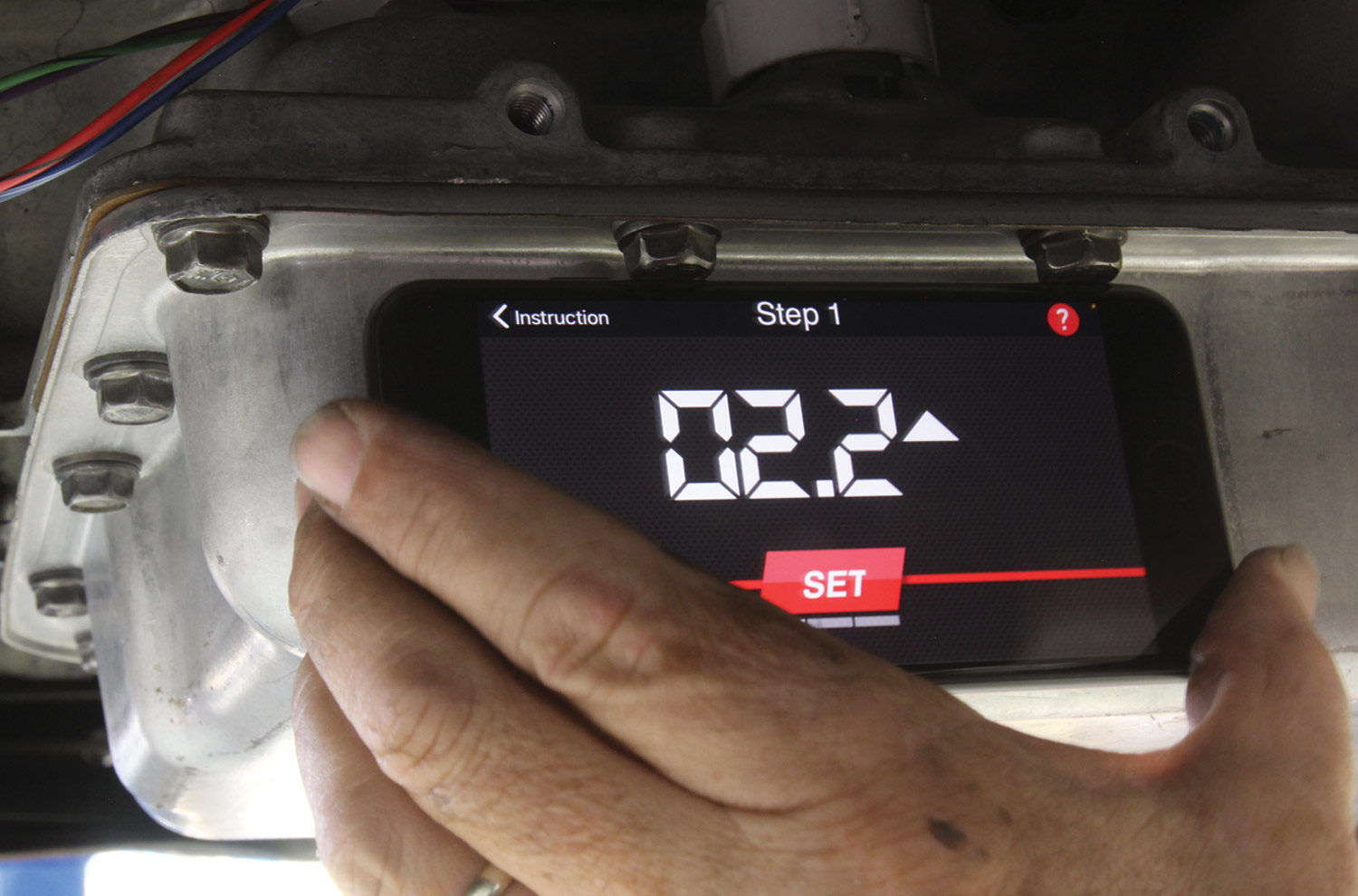
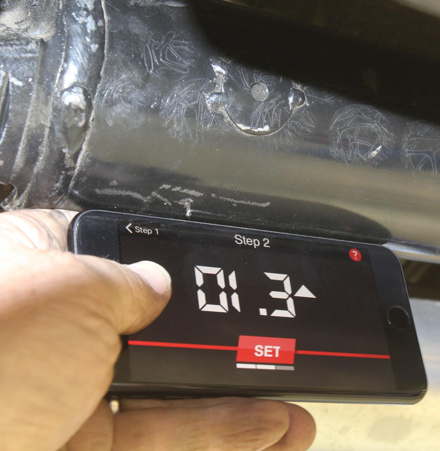
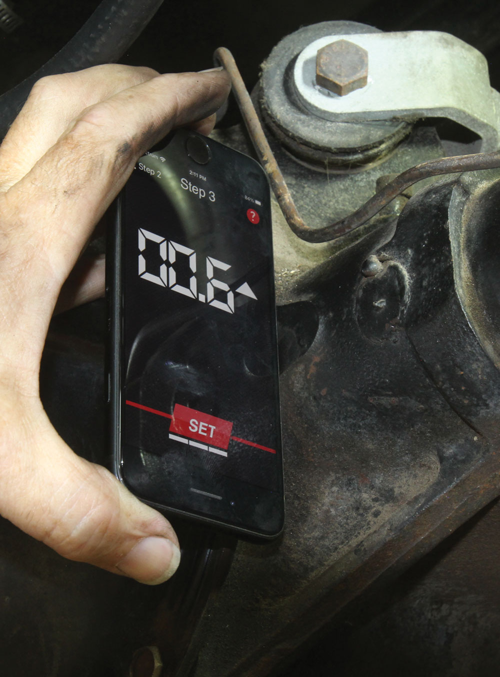
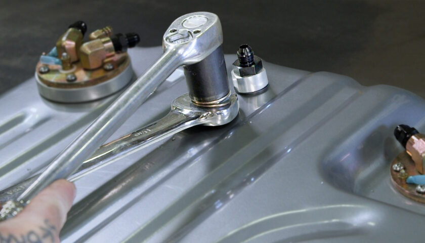
How to Measure Your Driveline Angle Using the TREMEC App