Driveshafts are an integral part of a vehicle’s drivetrain. They might seem simple at first glance, but there a few crucial details that need to be just right in order to avoid future problems. This tech piece aims to cover all the information anyone should know when trying to send power from their transmission to their rearend. Keep reading for all the driveshaft how to basics you should know.
U-Joint Basics
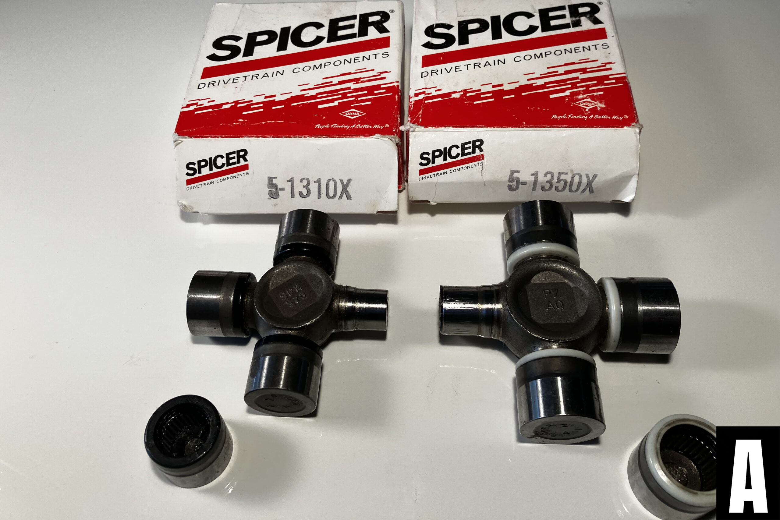
U-Joints come in many different sizes, but the ones you are most likely to come across are 1310, 1330 and 1350. Most common are the 1310 and 1330 series while higher performance applications use 1350. See the difference between the smaller 1310 series and larger 3150 series shown in photo A.
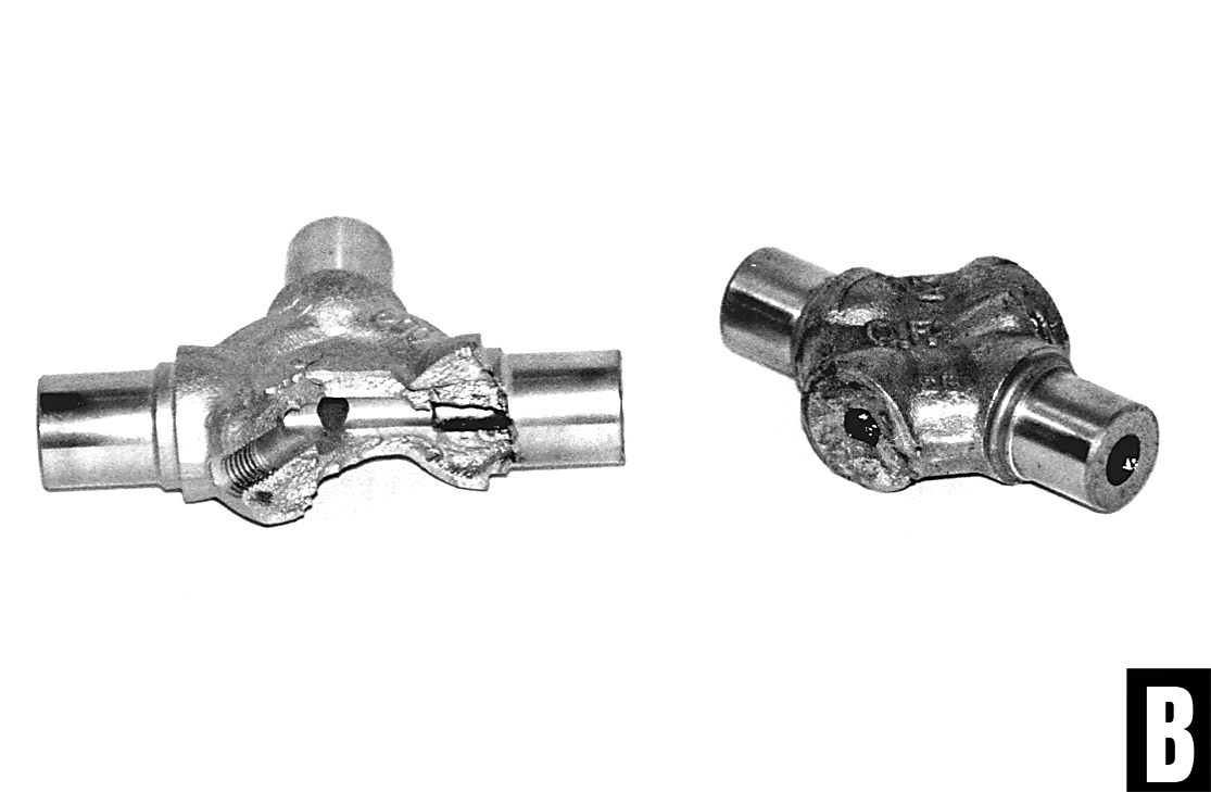
U-joints also come in maintenance free or greasable varieties. It’s generally agreed that the greasable versions are more prone to failure because of the hollow grease passages as seen in photo B. The maintenance free U-joints also benefit from higher-quality seals which result in better grease retention.
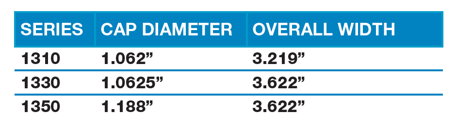
What Size U-Joints do I have? (U-joint Measurements)
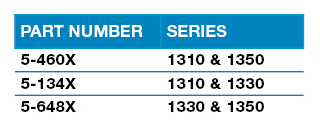
How to Adapt Two Different Size U-joints:
Spicer carries a few different options to combine the popular U-joint sizes we mentioned. Below are the part numbers and combinations.
Proper Driveshaft Angles
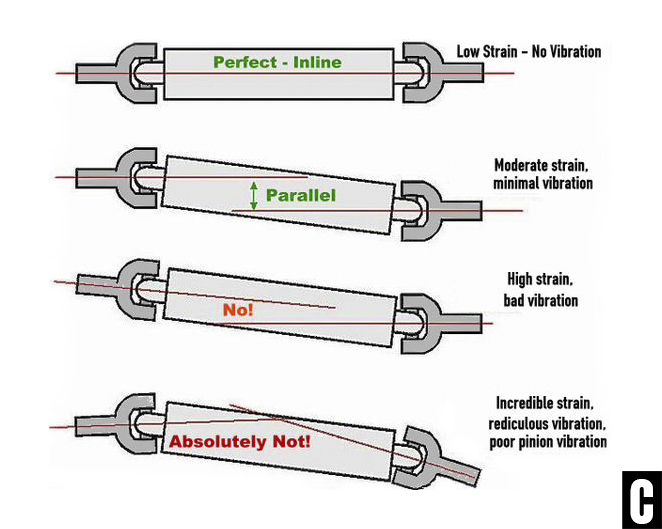
The trick to a vibration-free driveshaft is all in the angles. Specifically, the goal is to have the angle of the transmission and the angle of the differential as aligned as possible. In a perfect world, both angles will be exactly the same like the top image in photo C. But, if that were always the case we wouldn’t really need U-joints in the first place. The second example shows a more common alignment. In this case, if the transmission output shaft is pointing down (negative) 2-degrees, the third member should be pointing up (positive) 2-degrees.
Keeping these two angles parallel to each other works to cancel the motion of the U-joints and reduce vibrations. The further out of alignment these angles are (bottom two drawings in photo C), the worse the vibration felt in the vehicle and the more strain is placed on the driveline components.
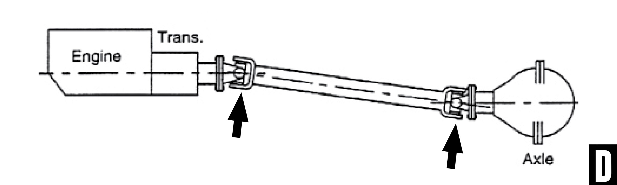
Another angle to pay attention to is the operating angle of the U-joints themselves. That angle is the difference between the transmission and the driveshaft or the driveshaft and the differential pinion (the arrows in photo D). During normal operation, the angle of the U-joints should not exceed 3-1/2 degrees.
How to Measure Driveshaft Angles
Important Note: The vehicle should be sitting at ride height for accurate measurements.
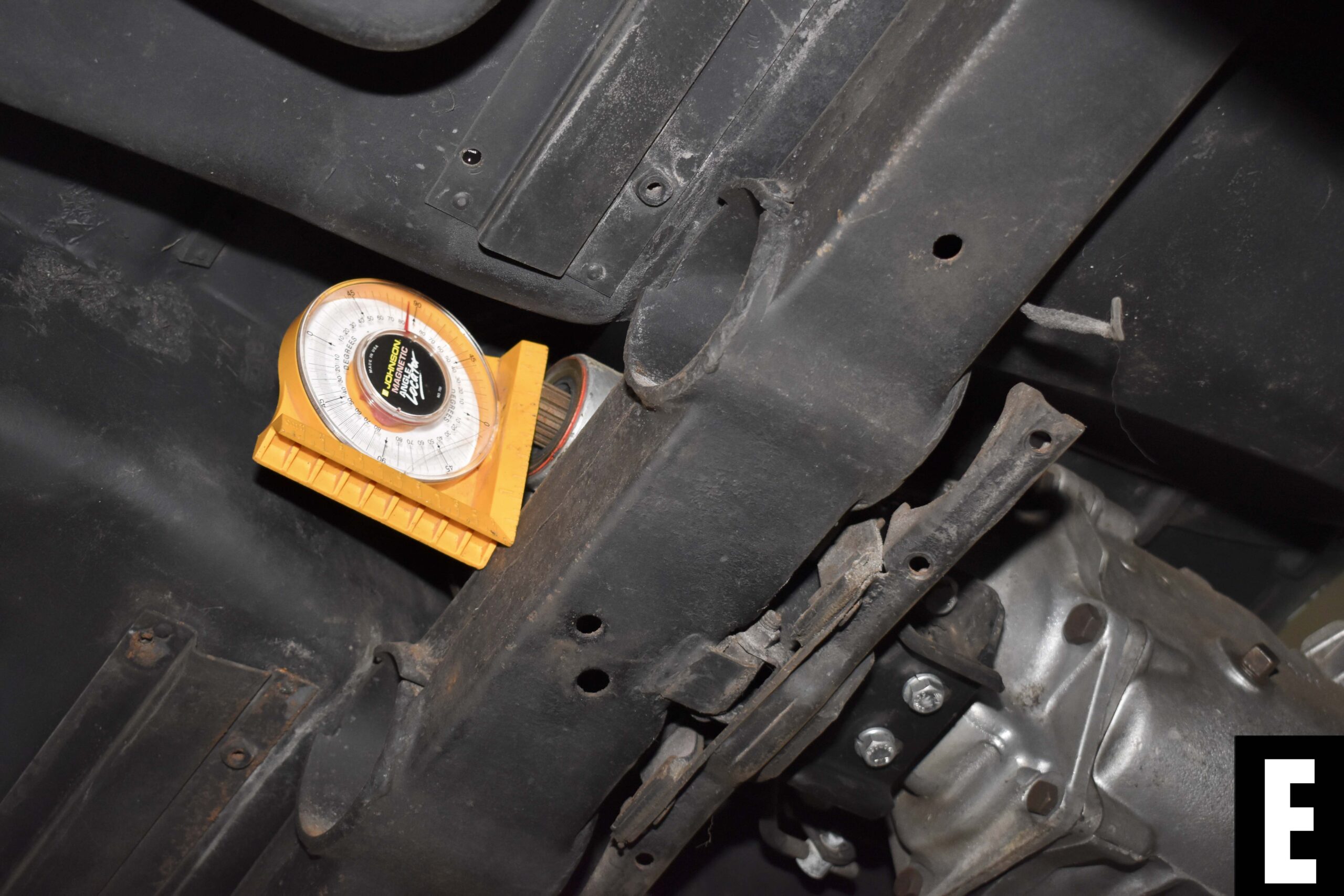
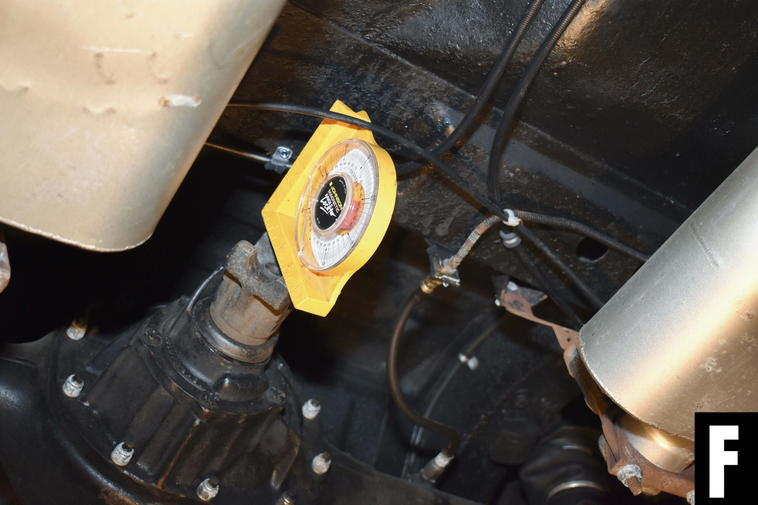
To measure the drivetrain angle, it is common to use an angle finder placed on the output shaft of the transmission. Although this often works, it’s better to use a machined surface like the starter mount since there can be droop in the output shaft (Photo E).
To measure the pinion angle, place the angle finder across the pinion flange (Photo F). The pinion angle should be within ½ to 1 degree of parallel to the drivetrain. As an example, if the drivetrain is measuring -2.0 degrees, the pinion should be +2.0 degrees but no more than +3.0 degrees or no less than +1.0 degrees.
Related Article: A Quick and Easy Way to Measure Driveshaft Angles
How to Fix Improper Driveshaft Angles
When a vehicle right height is modified, the pinion angle will change from its factory position. Depending on the severity, this could lead to unwanted vibrations and increased strain on the driveline components. To fix an improper driveshaft angle, it is easiest to change the pinion angle of the rearend.
For vehicles with multi-link rear suspension, pinion angle can be corrected easily by adjusting the length of the arms. If the vehicle has fixed factory arms, there are often aftermarket adjustable options available.
For vehicles with rear leaf spring suspension, the easiest way to change the pinion angle is by using pinion shims. The shims are typically available in 1-degree increments and install between the spring pad and top of the leaf springs or lowering blocks.
Once you know what rear suspension your vehicle has, refer to the section above titled “How to Measure Driveshaft Angles” to determine the amount of correction needed.
How to Measure for a New Driveshaft
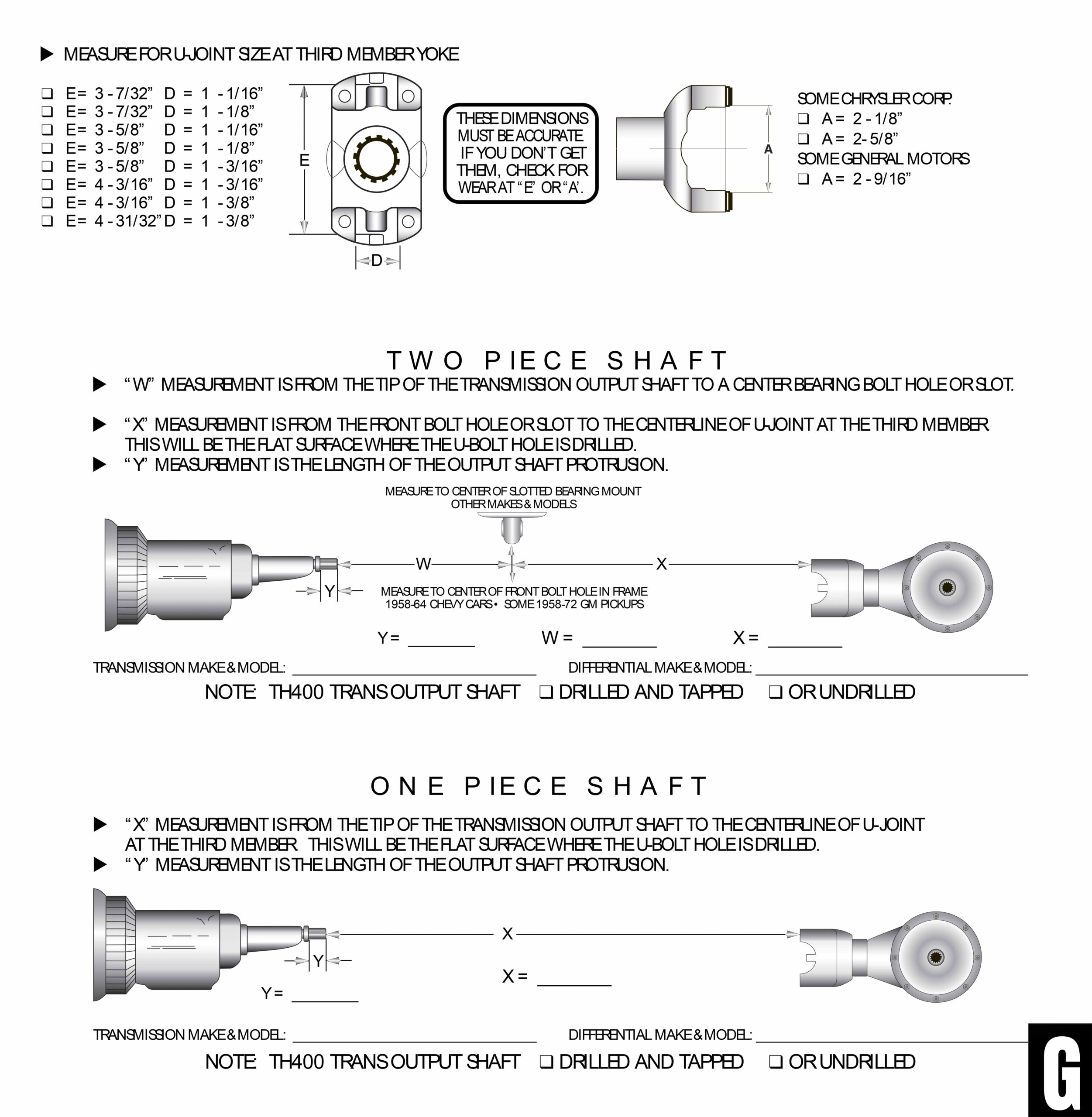
The exact measurements requested by your local driveshaft shop may vary slightly, but the order form provided by Inland Empire Driveline shows the information generally expected (photo G).
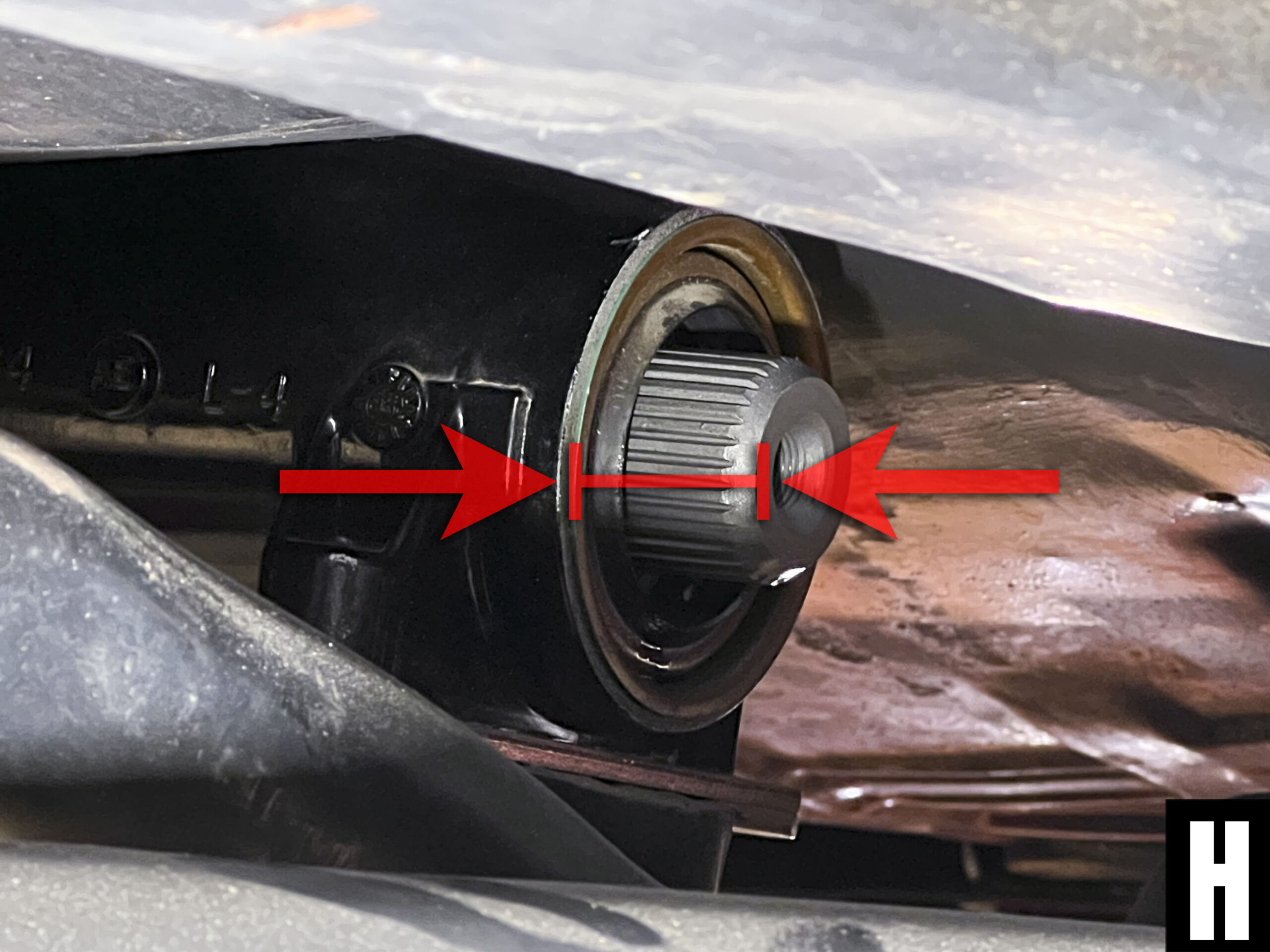
Begin by measuring the distance the output shaft protrudes from the tail shaft housing on your transmission (Photo H).
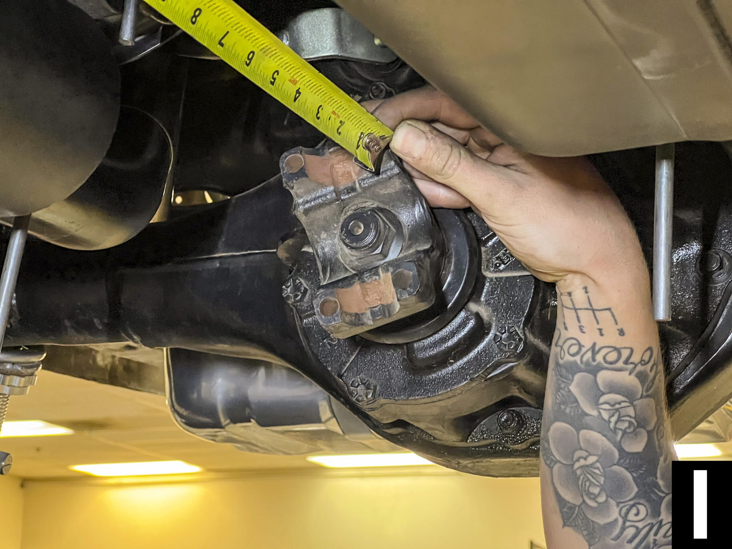
Then measure from the end of the output shaft to the centerline of the rear U-joint (Photo I).
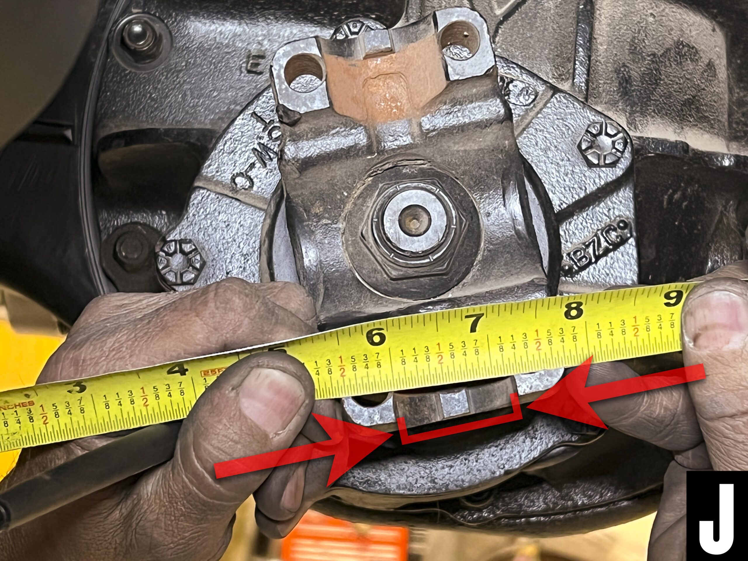
To measure for the proper U-joints, start by measuring the recess in the yoke to establish the diameter of the cups (Photo J).
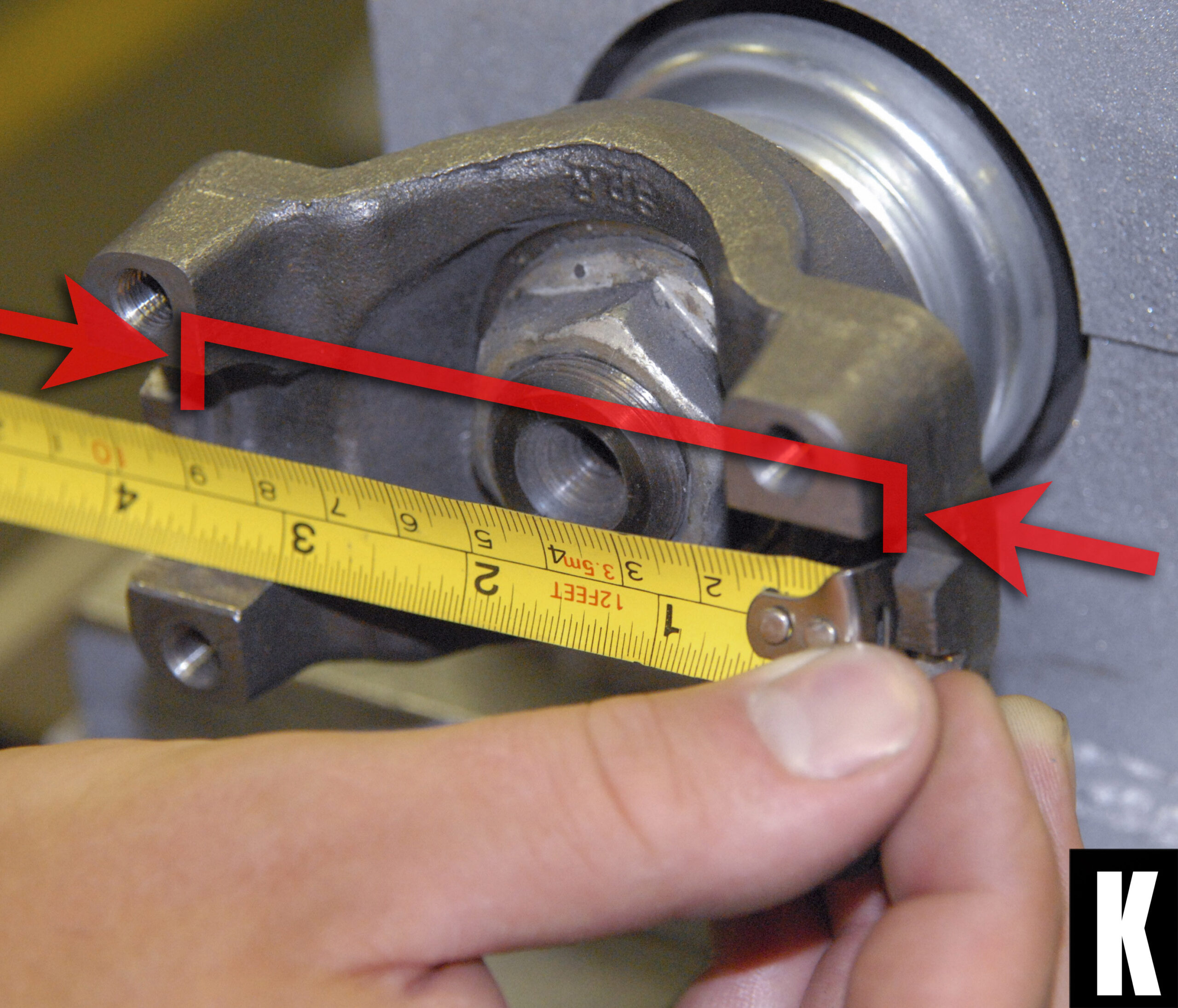
Then to get the width of the U-joint, measure the distance between the locating tabs on the pinion flange (Photo K).
Driveshaft Construction
Driveshafts can be constructed using a variety of materials with the most common being steel. Aluminum, carbon fiber and hybrid combinations of carbon fiber-wrapped aluminum are also occasionally used depending on the application. Regardless of materials used, there is an important factor to consider called critical speed. Without going too deep into the weeds, all you should know is that driveshafts become unstable at certain RPMs so the longer the driveshaft, the larger diameter the tubing needs to be. Then, beyond a certain length, it becomes necessary to move to a two-piece driveshaft.
Another factor to keep in mind is the transmission used. The torque requirements for a factory driveshaft without an overdrive gear are different than that of a more modern transmission equipped with overdrive. This is known as the half critical issue and is solved by sizing up the diameter of the driveshaft tubing.
These problems might sound a bit technical—because they are—but luckily you don’t need to understand it fully. A reputable driveshaft shop will know these limitations and build a driveshaft accordingly.
Photos courtesy of Ron Ceridono, Modern Rodding Magazine